1995 Ford Bronco Ignition System Wiring Diagram - TFI, ICM & PCM Schematic
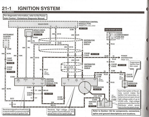
Ignition system schematic showing PCM, SPOUT check connector, Ignition Control Module (ICM), distributor, ignition coil and radio capacitor; coil produces up to 40,000-volt secondary pulses.
This document is page 21-1, "Ignition System," from the 1995 Ford Bronco wiring diagram manual. It shows the complete ignition system schematic, including the Powertrain Control Module (PCM), SPOUT check connector, Ignition Control Module (ICM) with its pinout (IDM/FTO 3, SPOUT 2, PIP 1, PWR 4, COIL 5, GND 6), the distributor with its connector pinout (PIP 8, IGN GND 7, SHIELD 2, PWR 1, GND 3), ignition coil, radio capacitor (which suppresses ignition system noise), and the engine compartment fuse box (fuse U, 20A, hot in start or run). Wire circuit numbers and color codes are labeled throughout, including 929 PK, 382 Y/BK, 395 GY/O, 259 O/R, 16 R/LG, 11 T/Y, 938 BK/LG, and 648 W/PK to the instrument cluster. Connector identifiers include C185, C1019, C250, C202F/M, C101M/F, C1021, C178F/M, C1017F/M, and C1008, along with splices S145, S148, S171, and S199. Explanatory callouts describe how the ICM switches ignition coil primary current and how up to 40,000-volt secondary pulses are routed through the distributor to fire the spark plugs. Cross-references point to power distribution (page 13-5), instrument cluster (page 60-5), and Section 152 for component locations.
Is this accurate? Sign in to help verify it.
Frequently asked questions
- What color is the SPOUT wire on a 1995 Bronco?
- The SPOUT circuit is wire 929 PK (pink), running from the PCM through the SPOUT check connector to pin 2 (SPOUT) of the Ignition Control Module.
- What is the ICM (Ignition Control Module) pinout on the 1995 Bronco?
- Per the diagram: pin 1 PIP, pin 2 SPOUT, pin 3 IDM (FTO), pin 4 PWR, pin 5 COIL, pin 6 GND. The ICM reference is 151-1 B10.
- Which fuse powers the 1995 Bronco ignition system?
- A 20A fuse (position U) in the engine compartment fuse box, hot in START or RUN, feeding circuit 16 R/LG (red/light green). See page 13-5 for power distribution.
- What wire goes from the ICM to the ignition coil?
- Circuit 938 BK/LG (black/light green) runs from ICM pin 5 (COIL) through connectors C178F/C178M to the ignition coil (C1008).
- What does the radio capacitor do in this ignition circuit?
- The diagram states it suppresses ignition system noise; it connects to the 12V (start or run) 16 R/LG circuit via connectors C1017F/C1017M.
Comments
More from this build













No comments yet.