Ford TFI Module Connector Pinout - 4.9L 5.0L 5.8L Wire Colors & Circuits
Reference · 1987-1991 BroncoAll 175 wiring diagrams


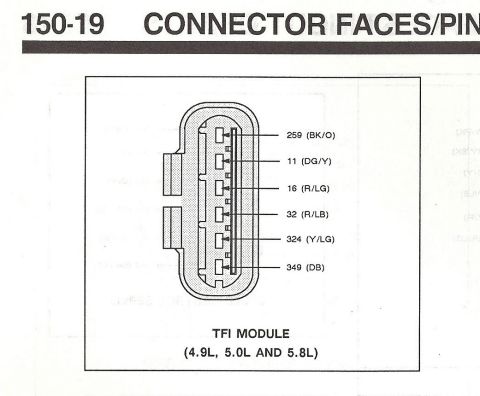
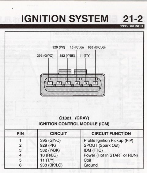
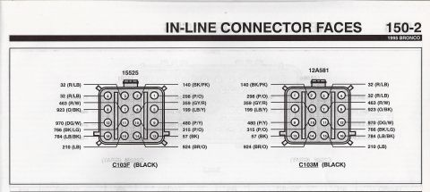












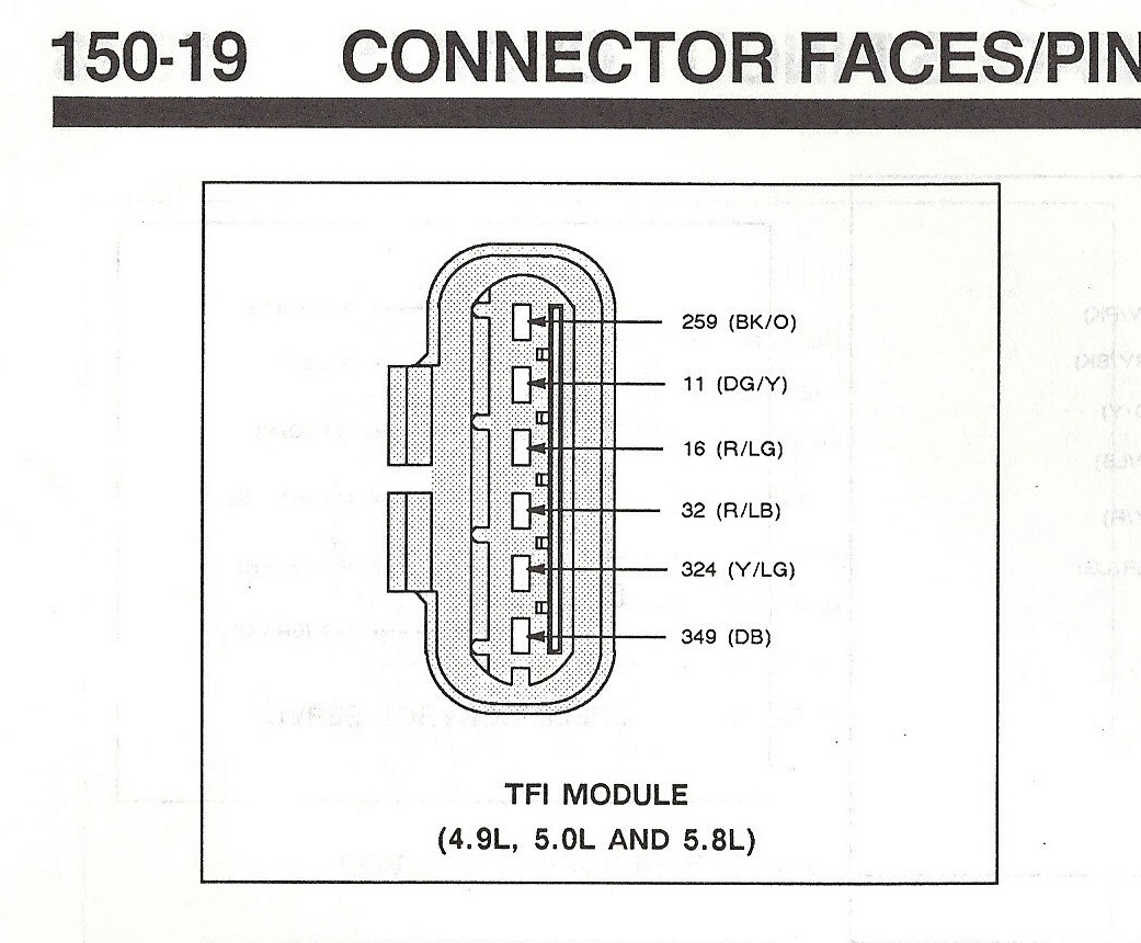
Connector faces/pinout (150-19) showing the TFI module connector terminals with circuit numbers and wire color codes for 4.9L/5.0L/5.8L.
Part of 1987-1991 Ford Bronco Wiring Diagrams
This document is a scanned page (page 150-19, titled "Connector Faces/Pins") from a Ford electrical/vacuum reference manual showing the connector face pinout for the TFI (Thick Film Ignition) module used on 4.9L, 5.0L and 5.8L engines. The illustration depicts the six-cavity TFI module connector as viewed at its face, with callout lines identifying each terminal by circuit number and wire color code: circuit 259 (BK/O, black/orange), circuit 11 (DG/Y, dark green/yellow), circuit 16 (R/LG, red/light green), circuit 32 (R/LB, red/light blue), circuit 324 (Y/LG, yellow/light green), and circuit 349 (DB, dark blue). A reader can use this diagram to identify which wire and circuit connects to each pin of the TFI module connector when diagnosing ignition problems, testing the module, or repairing wiring on Ford trucks with these engines. The page was uploaded as part of a set of TFI ignition reference documents for a 1990 Ford Bronco, and the engine applicability (4.9L, 5.0L, 5.8L) is consistent with Bronco/F-Series trucks of that era, though the page itself does not state a model year.
Applies to: Ford 4.9L/5.0L/5.8L (F-Series/Bronco) TFI module connector, manual page 150-19 (factory). Matches this vehicle.
Reviewed by the SuperMotors Editorial Team · Spotted an error? Suggest a correction
Is this accurate? Sign in to help verify it.
Frequently asked questions
- What are the wire colors on the Ford TFI module connector?
- Per the diagram: 259 (BK/O), 11 (DG/Y), 16 (R/LG), 32 (R/LB), 324 (Y/LG), and 349 (DB).
- Which engines does this TFI module connector diagram apply to?
- The diagram is labeled for the TFI module on 4.9L, 5.0L and 5.8L engines.
- What circuit numbers are on the TFI module connector?
- Circuits 259, 11, 16, 32, 324, and 349, listed from top to bottom on the connector face.
- How many pins does this TFI module connector have?
- The diagram shows six terminals with callouts on the connector face.






No comments yet.