Ford Black Remote-Mount TFI Ignition Module Wiring Schematic - EEC Pinout
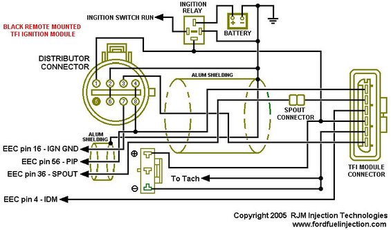
Wiring diagram of a remote-mounted TFI ignition module showing distributor connector, EEC pins, and shielding.
This document is a wiring schematic for the black remote-mounted TFI (Thick Film Ignition) module used on Ford EEC-IV ignition systems. It shows the 8-pin distributor connector (pins 1-8) and how its circuits route through aluminum-shielded cable sections to the TFI module connector, the SPOUT connector, the ignition coil (with a "To Tach" tap), the ignition relay, the battery, ground, and the ignition switch RUN circuit. Four EEC (engine computer) pin assignments are identified: EEC pin 16, IGN GND, EEC pin 56, PIP (Profile Ignition Pickup), EEC pin 36, SPOUT (Spark Output), and EEC pin 4, IDM (Ignition Diagnostic Monitor). The diagram is useful for diagnosing no-spark conditions, tracing PIP/SPOUT signal wiring, verifying which harness wires connect to which EEC processor pins, and understanding where the SPOUT connector sits in the circuit for base timing adjustment. The schematic was produced by RJM Injection Technologies (fordfuelinjection.com) and is dated 2005. It applies specifically to the black remote-mount style TFI module (as opposed to gray or distributor-mounted variants covered by companion diagrams in the same set). No specific vehicle year, model, or engine applicability is stated on the document itself.
Is this accurate? Sign in to help verify it.
Frequently asked questions
- Which EEC pins connect to the TFI ignition circuit in this schematic?
- The diagram identifies EEC pin 16 - IGN GND, EEC pin 56 - PIP, EEC pin 36 - SPOUT, and EEC pin 4 - IDM.
- How many pins does the distributor connector have?
- The distributor connector is shown with 8 pins, numbered 1 through 4 on the top row and 5 through 8 on the bottom row.
- Where does the SPOUT connector sit in the circuit?
- The SPOUT connector is shown inline in the harness between the distributor/shielded cable area and the TFI module connector, on the circuit that runs to EEC pin 36 - SPOUT.
- Where does the tachometer signal come from in this diagram?
- A "To Tach" lead is shown coming off the ignition coil circuit (the component drawn with + and - terminals).
- Which TFI module style does this schematic cover?
- It covers the black remote-mounted TFI ignition module, as stated in red text on the diagram.
Comments
More from this build














No comments yet.