Ford TFI Ignition Module Wiring Schematic - Black Distributor Mounted (EEC-IV)

Reference · 1987-1991 BroncoAll 175 wiring diagrams
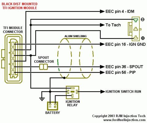
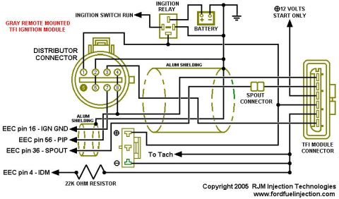
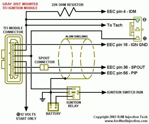
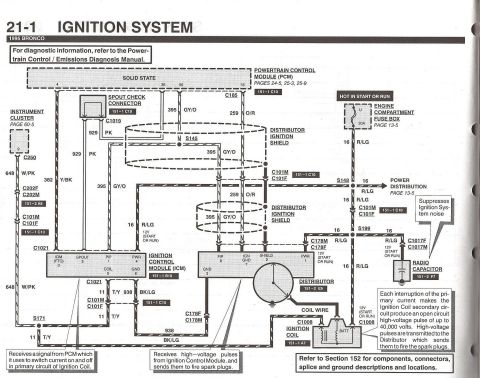
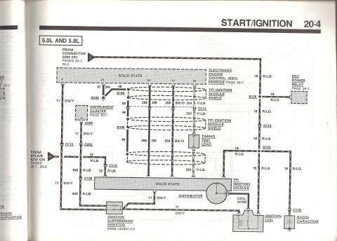












Wiring diagram of a distributor-mounted TFI ignition module showing EEC pins, SPOUT connector, ignition relay, and battery.
Part of 1987-1991 Ford Bronco Wiring Diagrams
This is a wiring schematic for the black distributor-mounted TFI (Thick Film Ignition) ignition module used on Ford EEC-IV fuel-injected vehicles. The diagram shows the six-pin TFI module connector on the left and traces each circuit to its destination: EEC pin 4 (IDM, Ignition Diagnostic Monitor), the tachometer feed, EEC pin 16 (IGN GND, ignition ground), EEC pin 36 (SPOUT, spark output), and EEC pin 56 (PIP, Profile Ignition Pickup). It also shows the SPOUT connector (an in-line jumper) in the SPOUT circuit, aluminum shielding around the PIP/SPOUT/IGN GND wiring, and the power supply path from the battery through the ignition relay and the ignition switch RUN circuit to the module. An ignition coil symbol is drawn at the upper right connected to the IDM/tach circuit. The diagram is credited "Copyright 2003 RJM Injection Tech, www.fordfuelinjection.com." A reader can learn which EEC-IV computer pins connect to each TFI module terminal, where the SPOUT jumper sits in the harness, which wires are shielded, and how the module receives switched power, useful for diagnosing no-spark, tach, or timing-related TFI problems on Fords with the black distributor-mounted module, such as the uploader's 1990 Bronco.
Is this accurate? Sign in to help verify it.
Frequently asked questions
- Which EEC pin does the TFI IDM signal go to?
- The IDM signal goes to EEC pin 4, and this circuit also feeds the tachometer.
- What EEC pin carries the SPOUT signal?
- SPOUT connects to EEC pin 36, passing through the in-line SPOUT connector.
- Which EEC pin is the PIP signal on?
- PIP (Profile Ignition Pickup) goes to EEC pin 56.
- How does the black distributor-mounted TFI module get power?
- Power comes from the battery through the ignition relay and the ignition switch RUN circuit.
- Are any TFI wires shielded?
- Yes, the diagram shows aluminum shielding (labeled ALUM SHIELDING) around the IGN GND, SPOUT, and PIP wiring between the module and the EEC.






No comments yet.