Home/
Registry/
Ford/
Bronco/
1992-1996/
1993 Ford Bronco/
Photo
supermotors.net/registry/media/927599
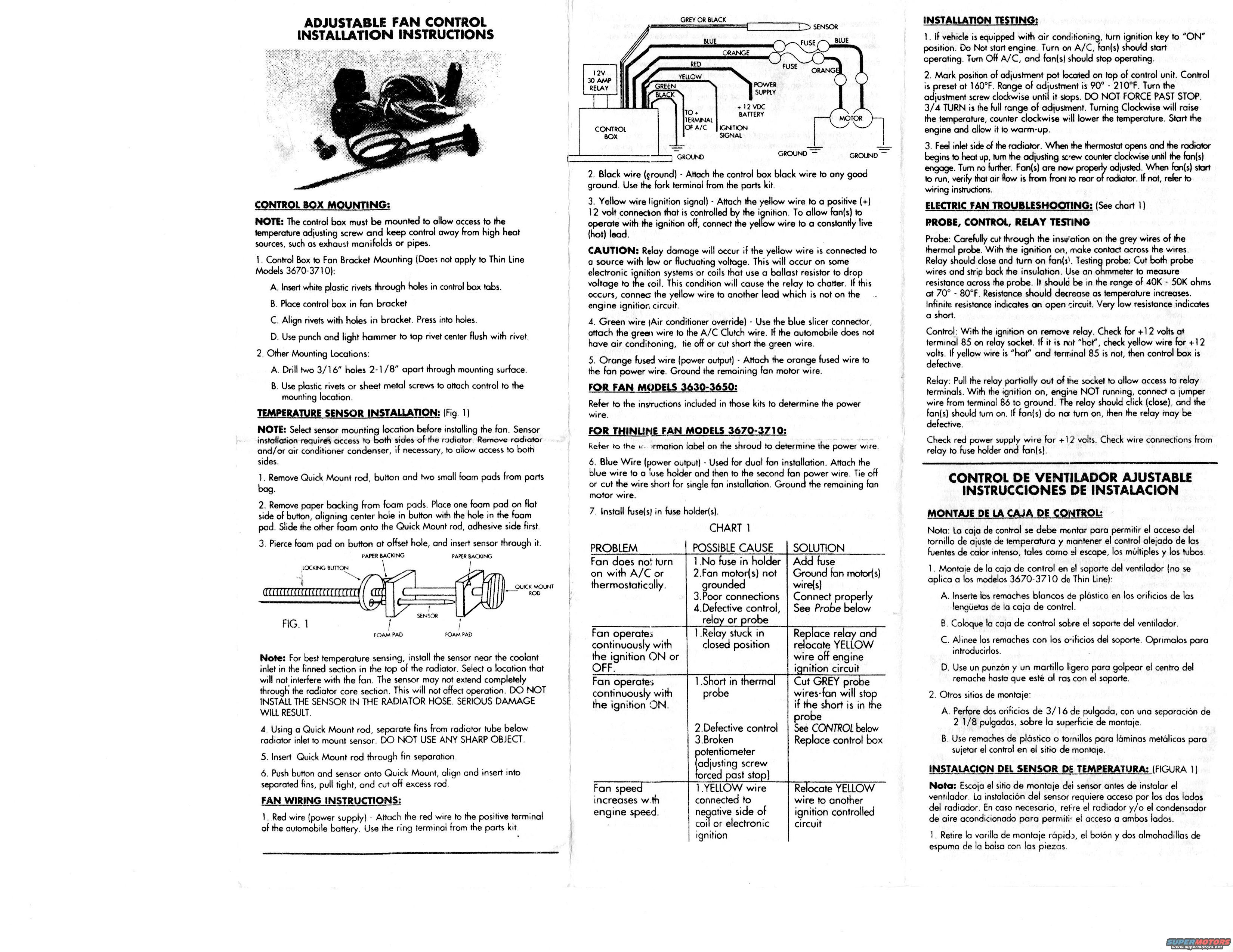
Adjustable Electric Fan Control Installation Instructions - Models 3630-3710
Reference · 1992-1996 BroncoAll 142 service procedures
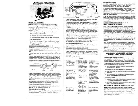







Installation instruction sheet for an adjustable electric fan control: control-box mounting, temperature sensor install, electrical/relay testing and a problem/cause/solution troubleshooting chart.
Part of 1992-1996 Ford Bronco Service Procedures
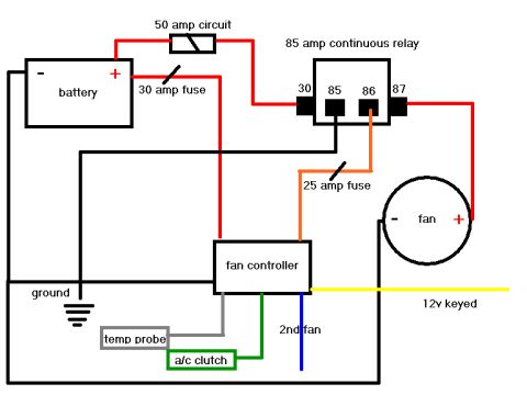
This document is the manufacturer's installation instruction sheet for an adjustable electric fan control (thermostatic controller) for automotive electric cooling fans, covering fan models 3630-3650 and Thin Line models 3670-3710. It explains how to mount the control box (either to the fan bracket with plastic rivets or elsewhere using two 3/16" holes 2-1/8" apart), how to install the radiator-fin temperature sensor with a Quick Mount rod and foam pads (with a warning never to install the sensor in the radiator hose), and complete fan wiring instructions by wire color: red (battery power), black (ground), yellow (ignition signal), green (A/C override to A/C clutch wire), orange fused wire (fan power output), and blue (second fan output for dual-fan setups). A wiring diagram shows the control box, 12V 30-amp relay, fuses, sensor, motor, and grounds. Installation testing explains the control is preset at 160°F with a 90°-210°F adjustment range over 3/4 turn of the adjustment screw. A troubleshooting chart (Chart 1) and probe/control/relay test procedures are provided, including probe resistance specs of 40K-50K ohms at 70°-80°F and relay terminal 85/86 checks. The final column repeats the mounting and sensor installation instructions in Spanish.
Is this accurate? Sign in to help verify it.
Frequently asked questions
- What temperature is the adjustable fan control preset to, and what is its adjustment range?
- The control is preset at 160°F, with an adjustment range of 90° to 210°F. The full range of adjustment is 3/4 turn of the adjustment screw; clockwise raises the temperature and counterclockwise lowers it. Do not force the screw past its stop.
- What does each wire color on the fan controller connect to?
- Red goes to the positive battery terminal (power supply), black to a good ground, yellow to an ignition-switched +12V source (ignition signal), green to the A/C clutch wire (A/C override), orange fused wire to the fan power wire, and blue to a fuse holder and second fan for dual-fan installations.
- Where should the temperature sensor be installed?
- Install the sensor near the coolant inlet in the finned section at the top of the radiator, in a spot that won't interfere with the fan, using the Quick Mount rod through separated fins. DO NOT install the sensor in the radiator hose, serious damage will result.
- How do I test the thermal probe?
- Cut both probe wires and strip back the insulation, then measure resistance across the probe with an ohmmeter. It should read 40K - 50K ohms at 70°-80°F, and resistance should decrease as temperature increases. Infinite resistance means an open circuit; very low resistance means a short.
- Why does the fan run continuously with the ignition on or off?
- Per Chart 1, this indicates the relay is stuck in the closed position. The solution is to replace the relay and relocate the YELLOW wire off the engine ignition circuit.






No comments yet.