Home/
Registry/
Ford/
Bronco/
1992-1996/
1993 Ford Bronco/
Photo
supermotors.net/registry/media/975558
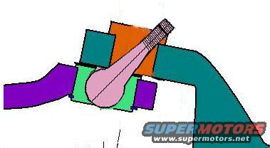
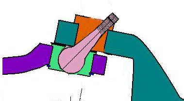
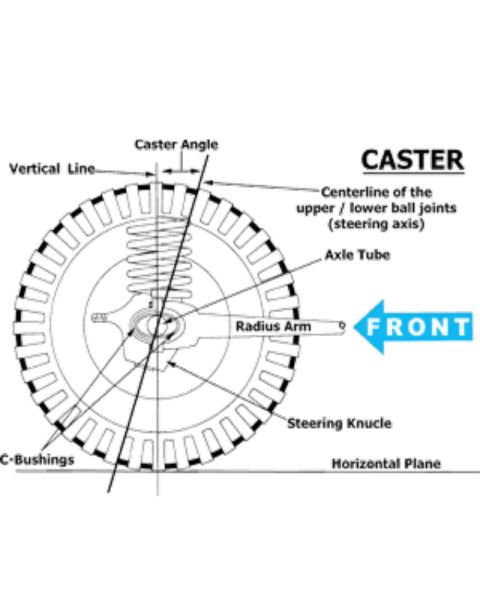
1993 Ford Bronco Ball Joint Angle Diagram - Front Suspension Schematic
Reference · 1992-1996 BroncoAll 95 schematics

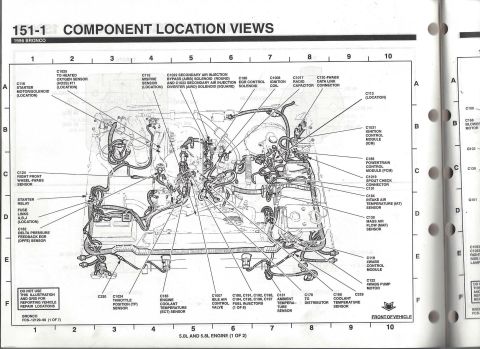
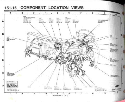
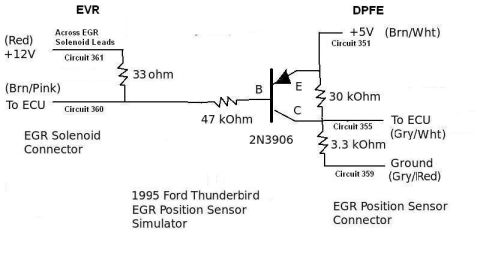

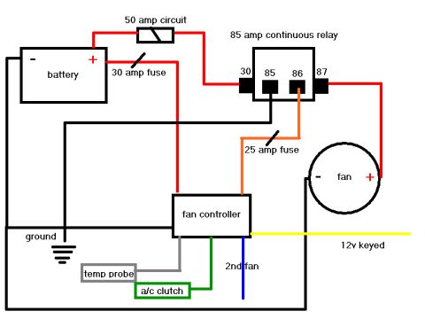
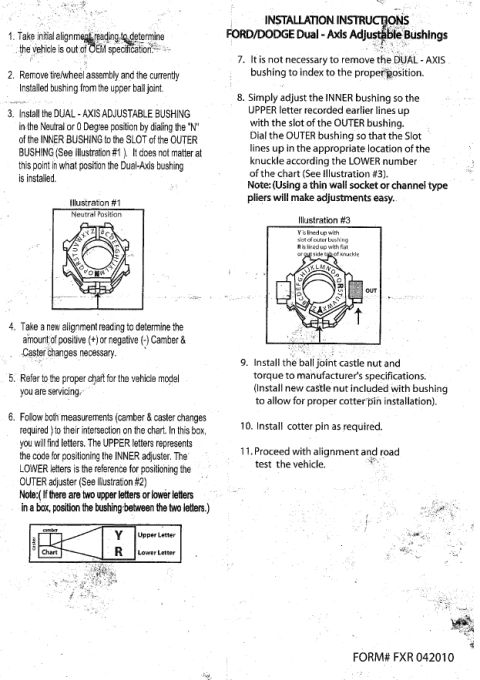
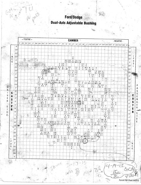
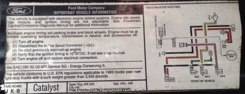

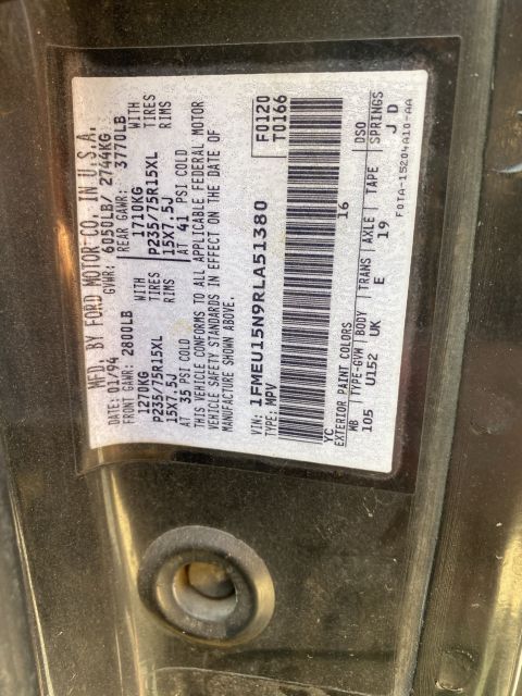




Simplified colored cross-section schematic illustrating a piston within a cylinder bore.
Part of 1992-1996 Ford Bronco Schematics
This document is an unlabeled color schematic illustration, uploaded to a 1993 Ford Bronco gallery under the filename 'Ball Joint angle.jpg'. It shows a simplified cross-sectional drawing of a ball joint assembly: a pink ball stud with a threaded upper shank passes at an angle through surrounding components drawn as colored blocks (teal for what appears to be the knuckle or axle structure, orange for a sleeve or bushing area at the top, green for the lower joint housing/boot area, and purple for an adjacent arm or beam). The drawing appears intended to demonstrate the angle at which the ball joint stud sits relative to the surrounding suspension components, likely as a visual companion to the camber bushing adjustment instructions found in the same album. Because the illustration contains no text, dimensions, torque specifications, part numbers, or year/model identification, no factual specifications can be extracted from it. A reader can only learn the general geometric relationship (angled orientation) of the ball joint stud within its mounting, useful as a conceptual aid when performing front-end alignment or camber adjustment work on a Twin Traction Beam style front suspension such as that used on the claimed 1993 Ford Bronco.
Is this accurate? Sign in to help verify it.
Frequently asked questions
- What does this diagram show?
- It is a simple color schematic showing a ball joint stud (pink, with threaded shank) installed at an angle within surrounding suspension components drawn as teal, orange, green, and purple blocks.
- Does the diagram include torque specs, part numbers, or measurements?
- No. The illustration contains no text, dimensions, torque values, or part numbers of any kind.
- How is the ball joint oriented in the drawing?
- The ball joint stud is shown tilted, with its threaded shank angled up and to the right through the upper (orange) component, illustrating the installed angle of the joint.
- Is this diagram part of a larger set?
- It was uploaded alongside a related document titled 'camber bushing adjust instruct.jpg', suggesting it serves as a visual aid for camber/ball joint adjustment instructions.






No comments yet.