Home/
Registry/
Ford/
Bronco/
1992-1996/
1993 Ford Bronco/
Photo
supermotors.net/registry/media/927464
Electric Fan Wiring Diagram - 85A Relay, Fan Controller & Fuses (Ford Bronco)
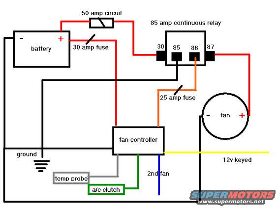
Electric cooling fan wiring diagram: battery feeds an 85A continuous relay (pins 30/85/86/87) through a 30A fuse, with a 25A fuse to fan controller, temp probe and A/C clutch on 12V keyed.
This document is a hand-drawn (computer-illustrated) wiring diagram for an electric cooling fan (e-fan) conversion, uploaded to the gallery of a 1993 Ford Bronco. It shows how to wire an aftermarket electric fan using an 85 amp continuous-duty relay, a 50 amp circuit protection device, a 30 amp fuse, and a 25 amp fuse, all controlled by a fan controller module. The battery positive feeds through the 50 amp circuit and 30 amp fuse to relay terminal 30 and to the fan controller. Relay terminal 87 powers the fan's positive terminal, terminal 86 receives a trigger signal from the fan controller through a 25 amp fuse (orange wire), and terminal 85 goes to ground. The fan negative and battery negative both connect to chassis ground. The fan controller has four additional connections: a gray wire to a temperature probe, a green wire to the A/C clutch (for fan-on with A/C), a blue wire labeled "2nd fan," and a yellow wire for a 12V keyed (ignition-switched) power source. A reader can learn the complete circuit layout, fuse amperages, relay pin assignments (30, 85, 86, 87), and wire color coding for installing a thermostatically controlled electric fan.
Is this accurate? Sign in to help verify it.
Frequently asked questions
- What relay is used in this electric fan wiring diagram?
- An 85 amp continuous relay, with terminals 30, 85, 86, and 87 shown. Terminal 30 gets fused battery power, 87 feeds the fan positive, 86 is triggered by the fan controller through a 25 amp fuse, and 85 goes to ground.
- What fuse sizes does this e-fan wiring diagram call for?
- A 50 amp circuit and a 30 amp fuse on the battery positive feed, plus a 25 amp fuse between the fan controller and relay terminal 86.
- What connections does the fan controller have?
- The fan controller connects to fused battery power (red), the relay trigger through a 25 amp fuse (orange), a temp probe (gray wire), the A/C clutch (green wire), a 2nd fan output (blue wire), and a 12V keyed source (yellow wire).
- How is the fan grounded in this diagram?
- The fan's negative terminal connects via a black wire to the same ground circuit as the battery negative and relay terminal 85, shown with a chassis ground symbol.
- What triggers the relay to turn the fan on?
- The fan controller sends power through a 25 amp fuse (orange wire) to relay terminal 86, energizing the relay so terminal 30 feeds terminal 87 and powers the fan.
Comments
More from this build







No comments yet.