1995 Ford Bronco 5.0L Engine Controls Wiring Diagram (Page 24-1) - PCM & MAF

Reference · 1987-1991 BroncoAll 175 wiring diagrams

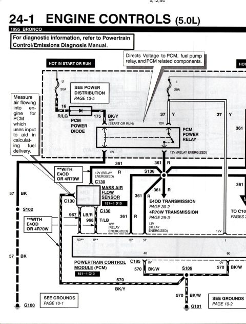
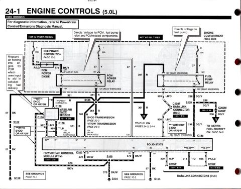












1995 Bronco 5.0L engine controls wiring (24-1) showing PCM power relay, fuel pump relay, PCM power diode, MAF sensor, data link connectors and 20A power-distribution feeds.
Part of 1987-1991 Ford Bronco Wiring Diagrams
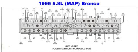
This is page 24-1 of the 1995 Ford Bronco Electrical and Vacuum Troubleshooting Manual, covering Engine Controls for the 5.0L engine. Dated 5/12/94, the wiring diagram shows power distribution to the Powertrain Control Module (PCM): a 20A fuse (position U, hot in start or run) feeds the PCM power diode via circuits 16 R/LG and 175 BK/Y to the PCM power relay coil, while 20A fuses (positions I and O, hot at all times) in the engine compartment fuse box feed circuit 37 Y to the PCM power relay and fuel pump relay. The energized PCM power relay outputs circuit 361 R, which powers the Mass Air Flow (MAF) sensor at connector C130, the E4OD/4R70W transmissions (pages 30-2 and 29-3), and PCM pins. The fuel pump relay output routes via circuits 926 LB/O to the Data Link Connector (C198F) and 238 DG/Y through C202M/C202F to the inertia fuel shutoff switch (page 24-8). PCM grounds are shown via circuits 57 BK and 570 BK/W to grounds G100, G101, and G104. Connector view references (151-1 D10, 151-1 C10, 151-1 B10, 151-2 A8) and PCM pin numbers are included, along with notes distinguishing wiring with and without E4OD/4R70W transmissions.
Is this accurate? Sign in to help verify it.
Frequently asked questions
- What fuses power the PCM and fuel pump relay on a 1995 Bronco 5.0L?
- Three 20A fuses in the engine compartment fuse box: fuse U (hot in start or run) feeds the PCM power diode and relay coil, and fuses I and O (hot at all times) feed circuit 37 Y to the PCM power relay and fuel pump relay.
- What wire circuit powers the Mass Air Flow sensor?
- Circuit 361 R (12V when the PCM power relay is energized) feeds the MAF sensor at connector C130; sensor signal wires shown are 967 LB/R and 968 T/LB (with E4OD or 4R70W).
- Where does the fuel pump relay output go?
- The relay output goes via circuit 926 LB/O to the Data Link Connector (C198F) and via circuit 238 DG/Y through splice S139 and connectors C202M/C202F to the inertia fuel shutoff, covered on page 24-8.
- How is the PCM grounded on the 1995 Bronco?
- Circuit 57 BK grounds through splice S102 to G100 and pin 20 to G104; circuits 570 BK/W from pins 40 and 60 join at splice S106 and ground at G101. Ground details are on pages 10-1 and 10-2.
- What does the PCM power relay do?
- Per the diagram callout, it directs voltage to the PCM, the fuel pump relay, and PCM-related components, outputting 12V on circuit 361 R when energized.






No comments yet.