1995 Ford Bronco Radio Wiring Diagram 130-4 - C258 Speaker Connector Pinout
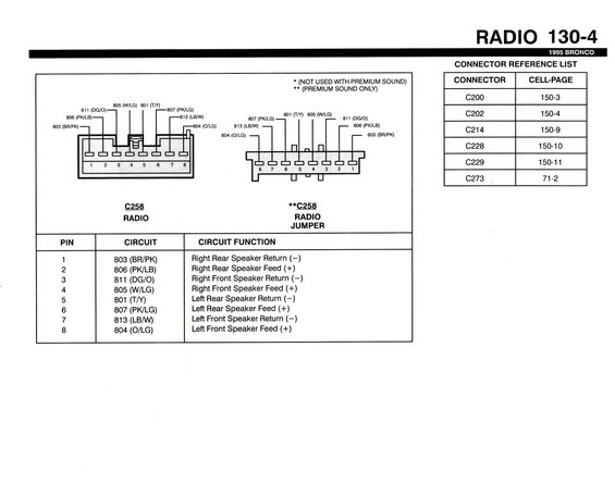
Radio C258 connector pin-out diagram for a 1995 Bronco with a pin-to-speaker-circuit function table and connector reference list.
This document is page 130-4 of the 1995 Ford Bronco factory wiring manual, covering the RADIO section. It shows the pinout for connector C258, the 8-pin radio speaker connector, in two versions: the standard radio connector (C258 RADIO, not used with premium sound) and the premium-sound-only radio jumper connector (**C258 RADIO JUMPER). Both connector faces are illustrated with pin numbers and circuit callouts. A pin/circuit/function table lists all eight speaker circuits: pin 1 = 803 (BR/PK) right rear speaker return (−); pin 2 = 806 (PK/LB) right rear speaker feed (+); pin 3 = 811 (DG/O) right front speaker return (−); pin 4 = 805 (W/LG) right front speaker feed (+); pin 5 = 801 (T/Y) left rear speaker return (−); pin 6 = 807 (PK/LG) left rear speaker feed (+); pin 7 = 813 (LB/W) left front speaker return (−); pin 8 = 804 (O/LG) left front speaker feed (+). A connector reference list cross-references connectors C200, C202, C214, C228, C229 and C273 to their cell-page locations elsewhere in the manual. Useful for identifying stereo speaker wire colors when replacing a radio or diagnosing speaker faults.
This document covers 1995, which may differ from this 1990 Ford Bronco.
Is this accurate? Sign in to help verify it.
Frequently asked questions
- What wire colors are the speaker wires on a 1995 Ford Bronco radio connector C258?
- Pin 1: 803 (BR/PK) right rear return; Pin 2: 806 (PK/LB) right rear feed; Pin 3: 811 (DG/O) right front return; Pin 4: 805 (W/LG) right front feed; Pin 5: 801 (T/Y) left rear return; Pin 6: 807 (PK/LG) left rear feed; Pin 7: 813 (LB/W) left front return; Pin 8: 804 (O/LG) left front feed.
- What is the difference between the two C258 connectors shown?
- The first C258 (RADIO) is marked * not used with premium sound; the second **C258 (RADIO JUMPER) is used with premium sound only. Both carry the same eight speaker circuits.
- Which pin is the left front speaker feed (+) on the 1995 Bronco radio?
- Pin 8, circuit 804 (O/LG: orange/light green).
- Where can I find the face views of related connectors like C200 or C273?
- The Connector Reference List gives cell-pages: C200 on 150-3, C202 on 150-4, C214 on 150-9, C228 on 150-10, C229 on 150-11, and C273 on 71-2.
Comments
More from this build














No comments yet.