Ford MAF Sensor Connector Pinout & Electrical Test Chart - Wire Colors
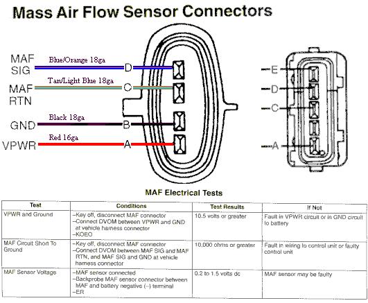
Mass air flow sensor connector wiring diagram showing color-coded MAF SIG, RTN, GND and VPWR wires with an electrical test conditions table.
This document is a wiring and testing reference for the Ford Mass Air Flow (MAF) sensor connector. It shows two connector diagrams identifying the pin assignments and wire specifications: pin D is MAF SIG (Blue/Orange 18-gauge), pin C is MAF RTN (Tan/Light Blue 18-gauge), pin B is GND (Black 18-gauge), and pin A is VPWR (Red 16-gauge). A second connector illustration shows pin positions labeled E, D, C, and A. Below the diagrams, a 'MAF Electrical Tests' table lists three diagnostic procedures: (1) VPWR and Ground test, with key off and the MAF connector disconnected, connect a DVOM between VPWR and GND at the vehicle harness connector with key on engine off (KOEO); expect 10.5 volts or greater, otherwise there is a fault in the VPWR or GND circuit to battery. (2) MAF Circuit Short To Ground, with key off and connector disconnected, measure between MAF SIG and MAF RTN, and MAF SIG and GND; expect 10,000 ohms or greater, otherwise there is a wiring or control-unit fault. (3) MAF Sensor Voltage: with the sensor connected, backprobe between MAF and battery negative with engine running; expect 0.2 to 1.5 volts DC, otherwise the MAF sensor may be faulty.
Is this accurate? Sign in to help verify it.
Frequently asked questions
- What are the wire colors for the Ford MAF sensor connector?
- MAF SIG is Blue/Orange 18ga (pin D), MAF RTN is Tan/Light Blue 18ga (pin C), GND is Black 18ga (pin B), and VPWR is Red 16ga (pin A).
- How do I test the VPWR circuit at the MAF connector?
- With the key off, disconnect the MAF connector, connect a DVOM between VPWR and GND at the vehicle harness connector, then key on engine off (KOEO). The reading should be 10.5 volts or greater; if not, there is a fault in the VPWR circuit or GND circuit to battery.
- What resistance should I see when checking the MAF circuit for a short to ground?
- With key off and the MAF connector disconnected, measure between MAF SIG and MAF RTN, and MAF SIG and GND at the harness connector. The result should be 10,000 ohms or greater; otherwise there is a fault in wiring to the control unit or a faulty control unit.
- What voltage should the MAF sensor output while the engine is running?
- With the MAF sensor connected, backprobe the connector between MAF and battery negative with the engine running; the reading should be 0.2 to 1.5 volts DC. If not, the MAF sensor may be faulty.
Comments
More from this build














No comments yet.