1995 Ford Bronco Radio Wiring Diagram 130-1 - Speaker & Power Circuits

Reference · 1987-1991 BroncoAll 175 wiring diagrams













Radio wiring diagram for a 1995 Bronco showing speaker circuits, fuse panel, illumination feed and color-coded wiring.
Part of 1987-1991 Ford Bronco Wiring Diagrams
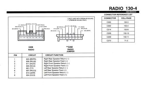
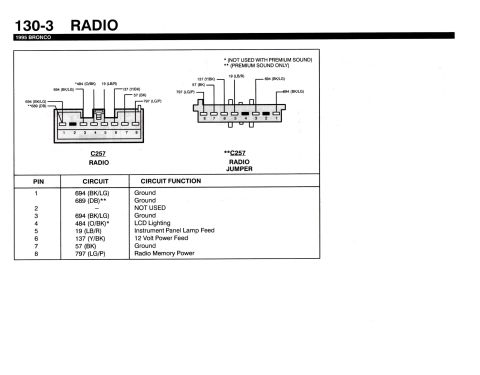
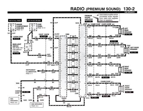
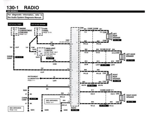
This is page 130-1 (RADIO) from the 1995 Ford Bronco factory electrical/vacuum troubleshooting manual (EVTM), showing the base (non-premium) radio wiring schematic. It documents the radio's power feeds: circuit 797 LG/P from the engine compartment fuse box (fuse A, 20A, hot at all times) and circuit 137 Y/BK from interior fuse panel fuse 11 (15A, hot in ACC or RUN). Circuit 484 O/BK comes from the main light switch for illumination dimming, circuit 19 LB/R feeds instrument illumination, and grounds run via circuit 57 BK to G201 (through splice S205 and connector C200) and circuit 694 BK/LG to G200. The speaker side shows all four speaker circuits with wire numbers, colors, and connectors: left rear speaker (801 T/Y, 807 PK/LG via C229/C326), left door speaker (804 O/LG, 813 LB/W via C214/C507), right rear speaker (806 PK/LB, 803 BR/PK via C327), and right door speaker (811 DG/O, 805 W/LG via C228/C607). Component location grid references (section 151) are given for each connector and speaker, plus cross-references to fuse box pages 13-7 and 13-15, main light switch testing (149-1), grounds (10-4, 10-9), and instrument illumination (71-1). A note directs diagnostics to the Audio System Diagnosis Manual.
This document covers 1995, which may differ from this 1990 Ford Bronco.
Is this accurate? Sign in to help verify it.
Frequently asked questions
- What fuses power the radio in a 1995 Ford Bronco?
- Two feeds: fuse A (20A) in the engine compartment fuse box (hot at all times) via circuit 797 LG/P, and fuse 11 (15A) in the interior fuse panel (hot in ACC or RUN) via circuit 137 Y/BK.
- What are the speaker wire colors for the 1995 Bronco radio?
- Left rear: 801 T/Y and 807 PK/LG (C326). Left door: 804 O/LG and 813 LB/W (C507). Right rear: 806 PK/LB and 803 BR/PK (C327). Right door: 811 DG/O and 805 W/LG (C607).
- Where does the 1995 Bronco radio ground?
- Circuit 57 BK from radio pin 7 runs through splice S205 and connector C200M/C200F to ground G201; circuits 694 BK/LG from radio pins 1 and 3 go to ground G200.
- What wire dims the radio illumination?
- Circuit 484 O/BK from the main light switch (connector C273) feeds radio pin 4; switch testing is covered on page 149-1.
- Which radio connectors are shown in this diagram?
- C257 is the power/ground connector and C258 is the speaker connector; component location reference for the radio is 151-3 A4.






No comments yet.