1995 Ford Bronco Radio Premium Sound Wiring Diagram 130-2 - Amp & Speakers

Reference · 1987-1991 BroncoAll 175 wiring diagrams

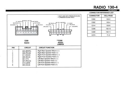
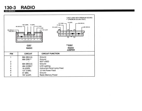
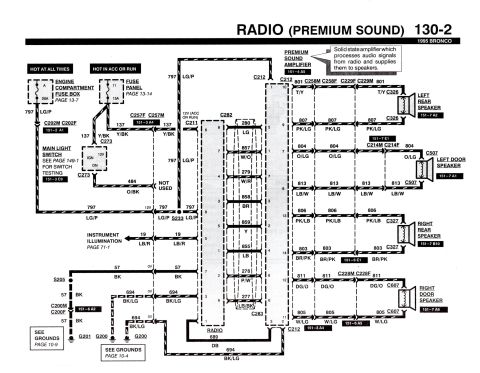
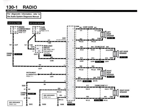












Premium sound radio wiring diagram for a 1995 Bronco showing the amplifier, speaker circuits and color-coded wiring.
Part of 1987-1991 Ford Bronco Wiring Diagrams
This is page 130-2 of the 1995 Ford Bronco electrical/vacuum troubleshooting manual (EVTM), showing the wiring diagram for the Radio with Premium Sound. It documents power feeds to the radio: circuit 797 (LG/P) from fuse A (20A) in the engine compartment fuse box (hot at all times, page 13-7) and circuit 137 (Y/BK) from fuse 11 (15A) in the interior fuse panel (hot in ACC or RUN, page 13-14), routed through the main light switch and connectors C202, C257, and C273. Grounds are circuits 57 (BK) to G201 and 694 (BK/LG) to G200, with references to grounds pages 10-9 and 10-4. The radio (connectors C282/C283) feeds the premium sound amplifier (component location 151-4 A5) through connector C212 using circuits 280 LG, 857 W/O, 279 W/R, 858 BR, 859 Y, 855 LB, 278 P/W, and 277 LB/BK. Amplifier outputs drive four speakers: left rear (801 T/Y, 807 PK/LG via C326), left door (804 O/LG, 813 LB/W via C507), right rear (806 PK/LB, 803 BR/PK via C327), and right door (811 DG/O, 805 W/LG via C607). Instrument illumination circuit 19 (LB/R, page 71-1) is also shown. The amplifier is described as a solid state unit that processes audio signals from the radio and supplies them to the speakers.
Is this accurate? Sign in to help verify it.
Frequently asked questions
- What fuses power the premium sound radio in a 1995 Bronco?
- A 20A fuse (position A) in the engine compartment fuse box provides hot-at-all-times power via circuit 797 LG/P, and a 15A fuse (position 11) in the fuse panel provides hot-in-ACC-or-RUN power via circuit 137 Y/BK.
- What are the speaker wire colors for the 1995 Bronco premium sound system?
- Left rear: 801 T/Y and 807 PK/LG; left door: 804 O/LG and 813 LB/W; right rear: 806 PK/LB and 803 BR/PK; right door: 811 DG/O and 805 W/LG.
- Which connector links the radio to the premium sound amplifier?
- Connector C212 carries the radio's output circuits (280 LG, 857 W/O, 279 W/R, 858 BR, 859 Y, 855 LB, 278 P/W, 277 LB/BK) to the premium sound amplifier, located per component view 151-4 A5.
- Where does the 1995 Bronco radio ground?
- Circuit 57 (BK) grounds at G201 (see grounds page 10-9) and circuit 694 (BK/LG) grounds at G200 (see grounds page 10-4).
- What does the premium sound amplifier do according to this diagram?
- It is a solid state amplifier which processes audio signals from the radio and supplies them to the speakers.






No comments yet.