Ford Bronco Fuel Pressure Regulator Diagram - O-Rings, Screws & Fuel Rail
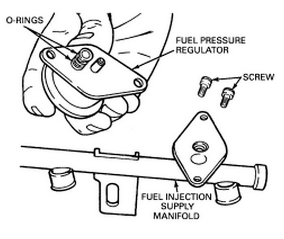
Exploded parts drawing of a fuel pressure regulator showing O-rings, mounting screws and the fuel injection supply manifold.
This document is a labeled exploded-view line drawing showing the fuel pressure regulator and its mounting on the fuel injection supply manifold (fuel rail). At the top, a hand is shown holding the fuel pressure regulator, with arrows identifying the O-rings on the regulator's nipple/inlet fittings. Two mounting screws are called out to the right. Below, the fuel injection supply manifold is drawn with the diamond-shaped regulator mounting flange/pad where the regulator attaches with the two screws. Injector cups and a vacuum fitting on the rail are also depicted but not labeled. A reader can learn the orientation and attachment method of the fuel pressure regulator: it seats into the supply manifold via O-ring-sealed ports and is secured with two screws to the flange on the fuel rail. The illustration is useful for identifying the parts involved when removing or replacing a fuel pressure regulator, including which seals (O-rings) must be present or replaced during reinstallation. The document contains no part numbers, torque specifications, year/model applicability, or written procedural steps, it is purely a parts identification/exploded diagram with four callout labels.
Is this accurate? Sign in to help verify it.
Frequently asked questions
- How is the fuel pressure regulator attached to the fuel rail?
- The diagram shows the fuel pressure regulator mounting to a flange on the fuel injection supply manifold with two screws.
- What seals are used on the fuel pressure regulator?
- The diagram calls out O-rings on the regulator, which seal its fittings where it seats into the fuel injection supply manifold.
- What parts are identified in this diagram?
- Four items are labeled: the O-rings, the fuel pressure regulator, the mounting screws, and the fuel injection supply manifold.
- How many screws hold the fuel pressure regulator in place?
- Two screws are shown in the diagram securing the regulator to the supply manifold.
Comments
More from this build














No comments yet.