1995 Ford Bronco Rear Suspension Schematic - Firestone Airbag & Control Arm
Reference · 1992-1996 BroncoAll 95 schematics


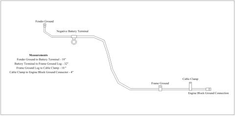









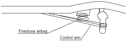
Simple labeled line diagram showing a Firestone airbag installed on a suspension control arm.
Part of 1992-1996 Ford Bronco Schematics
This document is a simple line-drawing schematic showing a rear suspension setup concept, apparently for a truck or SUV. The drawing depicts a side view of a vehicle frame/underbody area with two labeled callouts: a "Firestone airbag" positioned diagonally between the frame and a lower suspension member, and a "Control arm" running from the frame toward the axle area, which is drawn with a circular element (likely the axle tube or a bushing/shackle assembly). The sketch is unannotated beyond these two labels, there are no dimensions, part numbers, torque specifications, model years, or installation instructions visible. It was uploaded to a 1995 Ford Bronco gallery as "suspensionSetup.JPG," suggesting it illustrates the owner's planned or actual air-assist suspension arrangement, likely a custom or aftermarket configuration using a Firestone air bag (air spring) in conjunction with a control arm (possibly a radius arm or trailing arm). A reader can learn only the general placement relationship between the airbag and the control arm relative to the frame and axle; no specific fitment or technical data is provided by the document itself.
Is this accurate? Sign in to help verify it.
Frequently asked questions
- What components are labeled in this suspension schematic?
- Only two components are labeled: a Firestone airbag and a control arm.
- Where is the Firestone airbag positioned in this diagram?
- The airbag is shown mounted diagonally between the vehicle frame area and the lower suspension member, forward of the axle.
- Does this diagram include any measurements, part numbers, or torque specs?
- No. The drawing contains no dimensions, part numbers, torque values, or installation instructions, only the two component labels.
- What does the control arm connect to in the drawing?
- The control arm is drawn extending from the frame area rearward toward the axle region, which is depicted as a circular element.






No comments yet.