Transmission Lockup TCC/OD Case Connector Wiring Diagram - 52 & 44 Switches
Reference · 1987-1991 BroncoAll 175 wiring diagrams
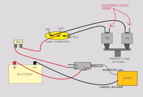





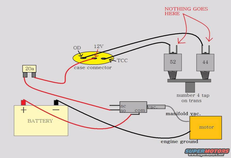
Wiring diagram showing battery, transmission case connector, relays and a vacuum switch for overdrive/TCC control.
Part of 1987-1991 Ford Bronco Wiring Diagrams
This is a color-coded, hand-drawn wiring diagram showing how to wire a transmission case connector for torque converter clutch (TCC) and overdrive (OD) lockup control. The transmission case connector (shown in yellow) has three pins labeled OD, 12V, and TCC. A red power wire runs from the battery positive terminal through a 20-amp blade fuse to the 12V pin of the case connector. Black wires from the OD and TCC pins route to two pressure switches, numbered 52 and 44, which mount on a bracket at the 'number 4 tap on trans.' A red callout labeled 'NOTHING GOES HERE' with arrows explicitly warns that the exposed upper terminals of the 52 and 44 pressure switches must be left unconnected. The diagram also shows a vacuum switch with terminals labeled nc, no, com, and a vac. port; battery positive feeds the 'com' terminal, and the vac. port connects via a gray line to manifold vacuum. The battery negative terminal is wired to engine ground at the motor. A reader learns the fuse size (20a), the case connector pinout (OD / 12V / TCC), the pressure switch identifiers (52 and 44) and their mounting location, and which switch terminals to leave empty.
Is this accurate? Sign in to help verify it.
Frequently asked questions
- What size fuse is used on the 12V feed to the case connector?
- A 20a (20 amp) fuse is shown in-line on the red wire between the battery positive terminal and the 12V pin of the case connector.
- What are the three pins on the transmission case connector?
- The case connector pins are labeled OD, 12V, and TCC.
- Where do the 52 and 44 pressure switches mount?
- They are shown mounted on a plate at the 'number 4 tap on trans' (the number 4 pressure tap on the transmission).
- What do the 'NOTHING GOES HERE' arrows mean?
- The red callout points to the upper terminals of the 52 and 44 pressure switches, indicating those terminals should be left unconnected.
- How is the vacuum switch connected?
- The switch has nc, no, and com terminals plus a vac. port. Battery positive (red wire) feeds the com terminal, and the vac. port connects by a gray line to manifold vac.






No comments yet.