Detroit Locker Differential Exploded View Diagram - Internal Parts Layout
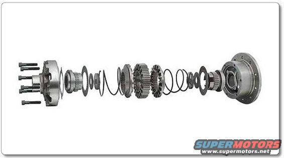
Exploded parts breakdown of a limited-slip differential carrier showing the gears, clutch plates, springs and case components laid out in assembly order.
This image is an unlabeled exploded-view photograph of a mechanical locking differential carrier assembly, showing all internal components laid out in assembly order along a horizontal axis. From left to right it depicts a case half with its retaining cap screws, a splined side gear/coupler, thrust washers, snap rings, coil springs, two toothed clutch/cam members that engage a central cam or spider unit, followed by mirrored springs, washers, snap rings, the opposite side gear/coupler, and the second case half with the ring-gear mounting flange. The photograph is useful for identifying the order and orientation of internal parts when disassembling or rebuilding this type of automatic locking differential, and for verifying that all components (springs, snap rings, washers, clutch members) are present. However, the document contains no text: there are no part numbers, torque specifications, callout labels, application years, or model information visible. It was uploaded to a 1995 Ford Bronco gallery alongside other axle and differential reference documents, and the filename suggests it depicts a Detroit Locker-style unit, but the image itself does not state any vehicle applicability.
Is this accurate? Sign in to help verify it.
Frequently asked questions
- What does this image show?
- An exploded view of a locking differential assembly with its internal components arranged in assembly order between the two case halves.
- What internal components are visible in the exploded view?
- Two case halves (one with cap screws, one with a ring-gear flange), side gear/couplers, thrust washers, snap rings, coil springs, toothed clutch/cam members, and a central cam/spider assembly.
- Does the image include part numbers or torque specs?
- No. The image contains no text, part numbers, callout labels, or torque specifications.
- Can this image be used during a rebuild?
- It can serve as a visual reference for the order and orientation of internal components during disassembly and reassembly, though it provides no written instructions.
Comments
More from this build







No comments yet.