SuperMotors SuperMotors SUPERMOTORS Search: try “orange Bronco on 35s”
Home/ Registry/ Ford/ Bronco/ 1992-1996/ “BRONCONUT”/ Photo supermotors.net/registry/media/985203

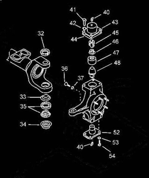
Kingpin Steering Knuckle Rebuild Exploded Diagram - Ford Bronco Front Axle
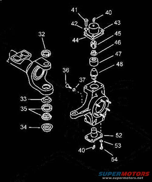
Exploded parts diagram of a steering knuckle and king pin assembly with numbered bushings, bearings and seals
Exploded parts diagram of a steering knuckle and king pin assembly with numbered bushings, bearings and sealsOriginal file
Exploded parts diagram of a steering knuckle and king pin assembly with numbered bushings, bearings and seals

Reference · 1992-1996 BroncoAll 169 exploded parts diagrams
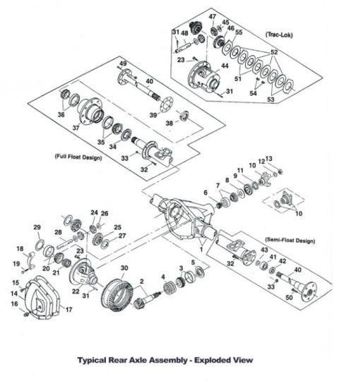
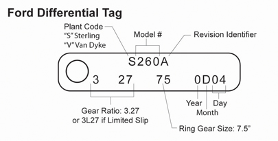
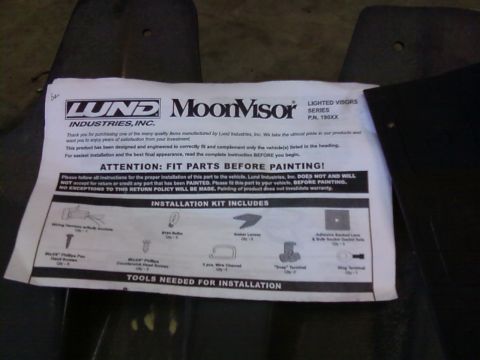
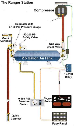
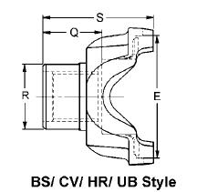
Ford Rear Axle Assembly Exploded View - Trac-Lok, Full Float & Semi-Float Kingpin Steering Knuckle Rebuild Exploded Diagram - Ford Bronco Front Axle Spring Loaded King Pin Assembly Cross-Section Diagram - Ford Solid Front Axle Dana 60 Front Axle Exploded Parts Diagram - Trac-Lok Differential & Locking Hub Detroit Locker Differential Exploded View Diagram - Internal Parts Layout Dana 60 Front Axle Exploded View Diagram - Trac-Lok Differential & Kingpin Parts Ford Bronco Front Axle Hub Bearings & Seals Exploded Diagram (Spindle & Hub) 2-Piece Wheel with Beadlock Insert - Exploded Parts Diagram 1996 Ford Bronco/F-150 Distributor Exploded Parts Diagram & Installation 03-07A-6 Ford Bronco Front Coil Spring & Shock Absorber Exploded Diagram (F2858-Q) Ford Bronco/F-Series Engine Block Ground Cable Diagram - Neg Battery Cable Views Instrument panel 04320 exploded view with finish panel 044D70, headlamp switch knob 11666 and mouldings 169exploded parts diagrams1992-1996 Ford Bronco More reference 1994-95 Mustang 5.0L EEC-IV CCRM Wiring Diagram & Pinout - FordWiring diagram Ford Differential Tag Decoder - Axle Gear Ratio, Ring Gear Size & Date CodeSpec plate Lund MoonVisor lighted visors P.N. 190XX instruction sheet with installation kit parts listManual page York Onboard Air Compressor Diagram - 2.5 Gallon Tank, Relay & Pressure SwitchSchematic Spicer End Yoke Dimension Diagram - BS/CV/HR/UB Style (S, Q, R, E Callouts)Blueprint Ford EEC-IV Output State Check & Cylinder Balance Test - Code Reader ProcedureService procedure 1994-1995 BMW 3 Series Owner's Manual Booklet Set - Warranty, Radio & AccessoriesBrochure 1995 Ford Bronco 5.8L Emissions/VECI Label - Vacuum Hose Routing DiagramVacuum routing Ford Bronco/F-Series Fuse 18 (10A) - Speedometer, Air Bag, Shift ControlFuse chart Rod Bolt Stretch Monitoring Chart - 8-Rod V8 Connecting Rod Bolt Record SheetTorque spec

Exploded parts breakdown of a steering knuckle and king pin assembly showing bushings, bearings, seals and spacers with numbered callouts.

Part of 1992-1996 Ford Bronco Exploded Parts Diagrams

AI caption · Photo 978 of 1094

This document is an exploded parts diagram illustrating the disassembly and component order of a front axle steering knuckle and kingpin assembly. It contains no written text apart from numbered callouts (32-37, 40-48, and 52-54) pointing to individual components. The left side of the drawing shows an axle yoke/inner shaft end with a cap or seal (item 32) above it and a stack of washers, seals, and a tapered bearing (items 33, 35, 34) below. The right side shows the steering knuckle itself, with an upper cap assembly held by fasteners (items 41, 40, 42, 43, 44), followed by an internal stack of bushings, a retainer, and the tapered kingpin (items 45, 46, 47, 48). Small pins or clips (items 36, 37) attach near the knuckle body. Beneath the knuckle, a lower bearing cap or plate is retained by bolts and washers (items 52, 53, 40, 54). A reader can learn the correct order and orientation of parts for rebuilding a kingpin-style steering knuckle, though no part numbers, torque specifications, or vehicle applicability information appear in the drawing itself. The uploader filed it under a 1995 Ford Bronco as a kingpin rebuild reference.

Is this accurate? Sign in to help verify it.

Frequently asked questions

What does this diagram show?
An exploded view of a front axle steering knuckle and kingpin assembly, showing the order of caps, seals, washers, bearings, bushings, and the tapered kingpin, identified by callout numbers 32-37, 40-48, and 52-54.
Does the diagram include part numbers or torque specs?
No. It contains only numbered callouts (e.g., 32, 41, 48, 54) with no part numbers, torque values, or written instructions.
What components sit above the steering knuckle in this diagram?
An upper cap/plate assembly with fasteners (items 40-44), followed by items 45-48, which are bushings, a retainer, and the tapered kingpin that seat into the top of the knuckle.
What is shown below the knuckle?
A lower cap or bearing plate (item 52) retained by fasteners and washers (items 40, 53, 54).

Comments

No comments yet.

More 1992-1996 Broncos