Spring Loaded King Pin Assembly Cross-Section Diagram - Ford Solid Front Axle

Reference · 1992-1996 BroncoAll 169 exploded parts diagrams
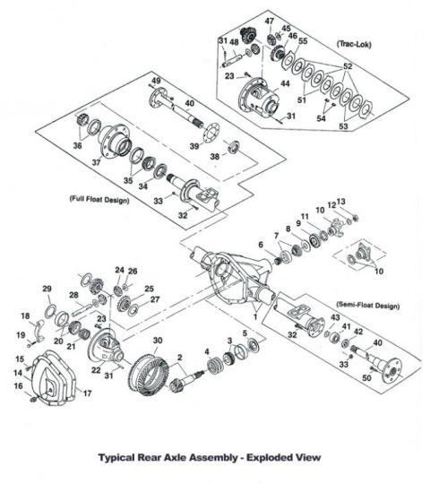
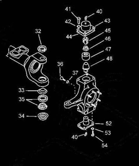
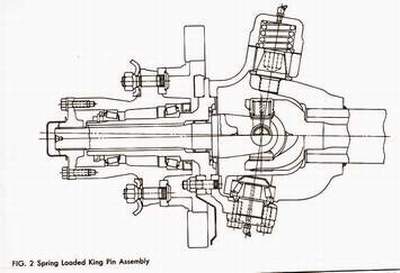
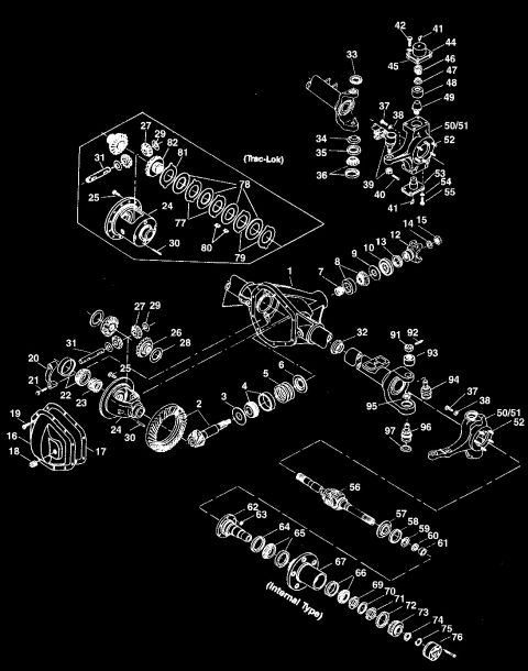
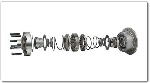
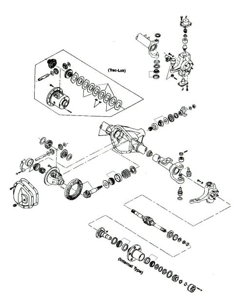
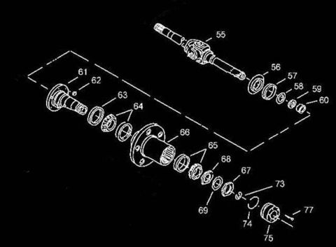









Assembly drawing of a spring-loaded king pin steering knuckle showing the bearing caps, springs and bolts, labeled Fig. 2.
Part of 1992-1996 Ford Bronco Exploded Parts Diagrams
This document is a scanned cross-sectional technical illustration labeled 'FIG. 2 Spring Loaded King Pin Assembly.' The line drawing shows a cutaway view of a spring-loaded king pin arrangement at the steering knuckle end of a solid front axle. Visible in the illustration are the axle housing tube extending from the right, the differential/knuckle ball area, the upper king pin with its retaining cap and stacked spring assembly at the top, the lower king pin bearing and cap secured with fasteners at the bottom, and the wheel hub, spindle, bearings, and hub components extending to the left. The drawing depicts how the king pin components, springs, bearings, seals, and fasteners fit together in section view. No part numbers, torque specifications, dimensions, or textual callouts are present in the scan other than the figure caption. The document does not state a year, make, or model. A reader can use this figure to understand the internal arrangement and relative positioning of the spring-loaded king pin components when disassembling or rebuilding a king-pin style front axle knuckle, such as identifying where the upper spring pack sits relative to the lower bearing cap. It was uploaded to a 1995 Ford Bronco gallery alongside other axle rebuild diagrams.
Is this accurate? Sign in to help verify it.
Frequently asked questions
- What does this diagram show?
- It is a cross-sectional illustration labeled 'FIG. 2 Spring Loaded King Pin Assembly,' showing a cutaway of a spring-loaded king pin at the steering knuckle of a solid front axle, including the upper spring stack, lower bearing cap, hub, and spindle area.
- Where is the spring located in a spring-loaded king pin assembly?
- Per the figure, the spring stack sits at the top of the assembly under the upper king pin cap, above the knuckle ball, while the lower king pin bearing and cap are at the bottom.
- Does this document include torque specs or part numbers?
- No. The only text visible is the caption 'FIG. 2 Spring Loaded King Pin Assembly'; no part numbers, torque values, or component labels are present.
- Does the diagram state what vehicle or axle it applies to?
- No. The scan contains no year, make, model, or axle designation, only the figure caption.






No comments yet.