Ford Bronco Front Axle Hub Bearings & Seals Exploded Diagram (Spindle & Hub)

Reference · 1992-1996 BroncoAll 169 exploded parts diagrams
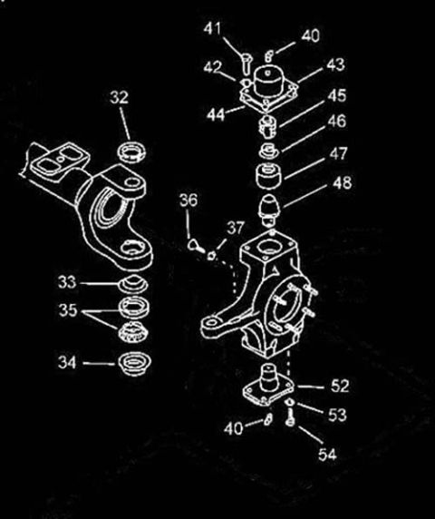
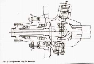
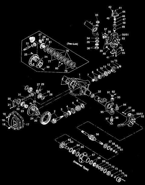
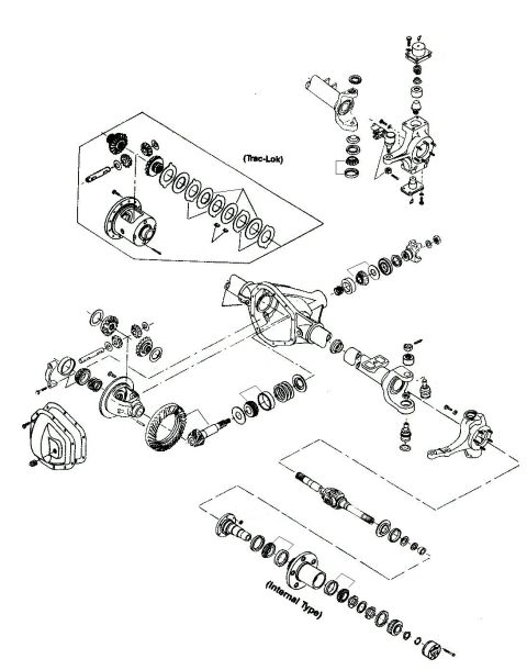
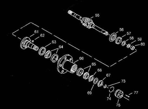









Exploded view of a front hub, spindle and axle shaft assembly with numbered part callouts.
Part of 1992-1996 Ford Bronco Exploded Parts Diagrams
This document is an exploded-view parts diagram of a front axle outer end assembly, showing the sequence of bearings, seals, and hub components along an axle shaft. It contains no written legend, part names, part numbers, torque specifications, or vehicle applicability text, only numbered callouts (55 through 77, with some numbers skipped: 70-72 and 76 are absent). The illustration shows, from upper right to lower left, a stub axle shaft with a universal joint (55), followed by a seal and bearing group (56-60), a wheel spindle (61) with a small pin or fastener (62), an inner seal (63), bearing components (64), and a splined wheel hub (66). Outboard of the hub are additional bearings, washers, and locknuts (65, 67, 68, 69), followed by a snap ring (73), a retaining ring (74), a locking hub or drive flange assembly (75), and small retaining hardware (77). The diagram illustrates the correct assembly order of front hub bearings and seals but a reader must consult an accompanying legend (not included in this scan) to identify each numbered component by name or part number. It was uploaded to document bearings and seals for a 1995 Ford Bronco front axle.
Is this accurate? Sign in to help verify it.
Frequently asked questions
- What does this diagram show?
- An exploded view of a front axle outer end: an axle shaft with universal joint, spindle, bearings, seals, wheel hub, locknuts, snap ring, and a locking hub assembly, identified only by callout numbers 55-77.
- Does the diagram list part names or part numbers?
- No. It contains only numbered callouts (55-69, 73, 74, 75, 77) with no legend, part names, or part numbers.
- What is the order of components between the spindle and the hub?
- Per the diagram, spindle (61) with a small pin/fastener (62) is followed by a seal (63) and bearing components (64) before the splined wheel hub (66).
- Which callout numbers are shown at the outer end of the assembly?
- After the hub (66), the diagram shows items 65, 68, 67, 69, then snap ring 73, ring 74, the hub/cap assembly 75, and small fasteners 77.






No comments yet.