DPDT Rocker Switch Wiring Diagram - DC Motor Polarity Reversing Hookup
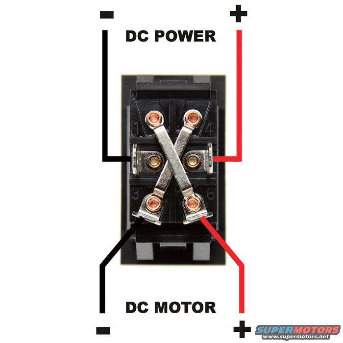
Reference · 1987-1991 BroncoAll 175 wiring diagrams
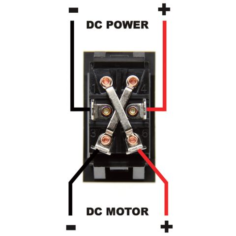
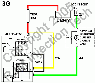


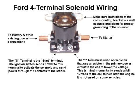





Wiring diagram of a rocker switch showing terminal connections from DC power to a DC motor with positive and negative leads.
Part of 1987-1991 Ford Bronco Wiring Diagrams
This document is a wiring diagram/photograph showing how to wire a 6-terminal double-pole double-throw (DPDT) rocker switch to reverse the polarity of a DC motor. The switch is shown from the rear with its six screw terminals, numbered 1 through 6 in the molded housing (1 and 4 across the top, 3 and 6 across the bottom, middle pair between them). Two metal jumper straps are installed in an X (cross-over) pattern connecting the top-left terminal to the bottom-right terminal and the top-right terminal to the bottom-left terminal. DC power input is connected to the middle pair of terminals: black (negative) to the middle-left terminal and red (positive) to the middle-right terminal, as labeled "DC POWER" with − and + symbols at the top. The DC motor leads connect to the bottom pair of terminals: black (negative) on the left and red (positive) on the right, labeled "DC MOTOR" with − and + symbols at the bottom. A reader learns the correct terminal assignments and jumper configuration to make a reversing (forward/reverse) switch for any DC motor application, such as power windows, winches, linear actuators, or tilt motors.
Is this accurate? Sign in to help verify it.
Frequently asked questions
- Where does DC power connect on a 6-terminal DPDT reversing switch?
- Per the diagram, DC power connects to the middle pair of terminals: the black (−) wire to the middle-left terminal and the red (+) wire to the middle-right terminal.
- Where do the DC motor wires connect?
- The motor wires connect to the bottom pair of terminals: black (−) to the bottom-left terminal and red (+) to the bottom-right terminal, as labeled "DC MOTOR" at the bottom of the diagram.
- How are the jumper straps installed to make the switch reverse polarity?
- Two metal jumper straps are installed in an X (cross-over) pattern: one connects the top-left terminal to the bottom-right terminal, and the other connects the top-right terminal to the bottom-left terminal.
- How are the switch terminals numbered?
- The switch housing shows molded terminal numbers, with 1 and 4 across the top row and 3 and 6 across the bottom row (six terminals total in three rows of two).






No comments yet.