Home/
Registry/
Ford/
Bronco/
1987-1991/
1990 Ford Bronco/
Photo
supermotors.net/registry/media/990412
Ford Bronco Frame Swap Sketch - Old vs New Frame Splice, Gusset & Crossmember
Reference · 1987-1991 BroncoAll 112 schematics









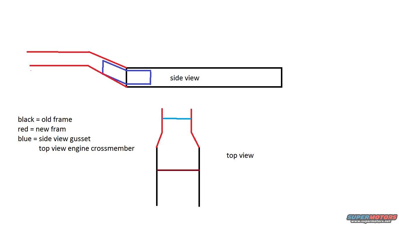
Fabrication schematic showing side and top views of a frame modification with color-coded old frame, new frame, and gusset.
Part of 1987-1991 Ford Bronco Schematics
This is a simple hand-drawn digital sketch (MS Paint-style schematic) illustrating a frame modification, apparently for a frame swap or frame extension/kick-up on a vehicle. Two views are shown. The 'side view' depicts a black horizontal rectangle representing the old frame rail, with red lines representing the new frame rail angling upward and forward from it, and a blue parallelogram/rectangle labeled as a gusset plate reinforcing the joint where the new frame section meets the old one. The 'top view' shows two black parallel frame rails transitioning (in red) to a narrower forward section, with a light blue line across the front labeled as the engine crossmember and a dark red line as an additional crossmember within the black (old) frame section. A legend explains the color coding: black = old frame, red = new frame ('fram' as written), blue = side view gusset / top view engine crossmember. The drawing contains no dimensions, part numbers, torque values, or vehicle-specific applicability text; it serves as a conceptual plan for splicing a new front frame section onto an existing frame with gusset reinforcement.
Is this accurate? Sign in to help verify it.
Frequently asked questions
- What do the colors mean in this frame diagram?
- Per the legend: black = old frame, red = new frame, and blue = the gusset in the side view or the engine crossmember in the top view.
- What views does the sketch include?
- Two views are shown: a 'side view' of the frame splice with a blue gusset at the joint, and a 'top view' showing the frame rails and engine crossmember.
- Where is the gusset located?
- In the side view, the blue gusset is drawn at the angled joint where the red new frame section meets the black old frame rail.
- Does the diagram give any dimensions or part numbers?
- No. The sketch is conceptual only, it contains no measurements, part numbers, or torque specifications.






No comments yet.