Home/
Registry/
Ford/
Bronco/
1987-1991/
1990 Ford Bronco/
Photo
supermotors.net/registry/media/772708
Ford Bronco Floor Pan Patch Panel Repair Diagram - Metal Tabs & Screws

Reference · 1987-1991 BroncoAll 95 service procedures
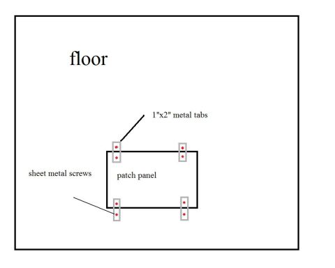

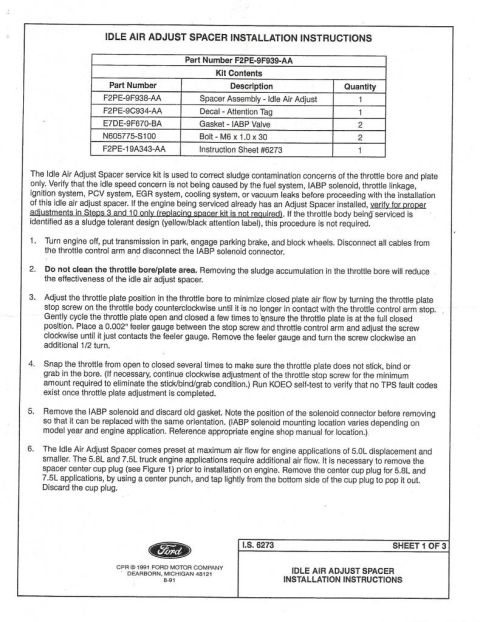
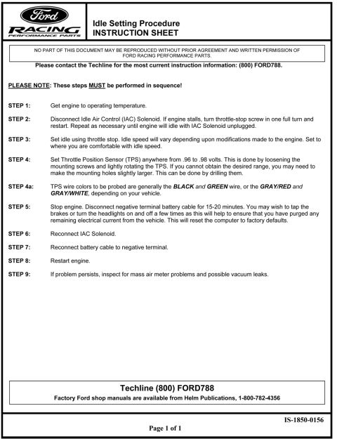
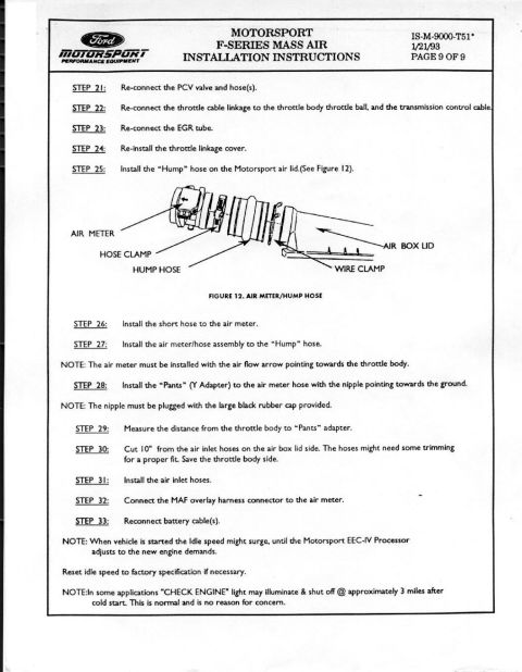









Repair diagram showing a floor patch panel secured with 1x2 inch metal tabs and sheet metal screws.
Part of 1987-1991 Ford Bronco Service Procedures
This is a simple hand-drawn diagram (not a factory service document) illustrating a floor pan patch panel repair method. The drawing shows a large rectangle labeled "floor" representing the vehicle floor, with a rusted-out or cut opening in the floor represented by a smaller rectangle. A rectangle labeled "patch panel" is positioned over the opening. Four small gray rectangles labeled "1"x2" metal tabs" are placed at the four corners, straddling the edge between the patch panel and the surrounding floor metal. Each tab shows two red dots indicating fastener locations, with a leader line labeling them as "sheet metal screws", one screw goes into the patch panel and one into the original floor, so the tabs bridge and secure the patch. A reader can learn a basic no-weld technique for repairing a rusted floor section: cut a patch panel to size, back it with four 1"x2" metal tabs at the corners, and fasten each tab with two sheet metal screws (eight screws total shown). The document was uploaded to the gallery of a 1990 Ford Bronco, but the drawing itself contains no vehicle-specific information, year, model, or part numbers.
Is this accurate? Sign in to help verify it.
Frequently asked questions
- How is the patch panel attached to the floor in this diagram?
- The patch panel is secured using 1"x2" metal tabs placed at the corners, each fastened with sheet metal screws (shown as two red dots per tab).
- What size are the metal tabs used to hold the floor patch panel?
- The diagram labels them as 1"x2" metal tabs.
- How many metal tabs are shown holding the patch panel?
- Four tabs are shown, one near each corner of the patch panel, bridging the patch and the surrounding floor.
- What fasteners are used in this floor repair method?
- Sheet metal screws, the diagram shows two screw locations (red dots) per tab, one into the patch panel side and one into the floor side.






No comments yet.