Home/
Registry/
Ford/
Bronco/
1992-1996/
1995 Ford Bronco/
Photo
supermotors.net/registry/media/1008780
1995 Ford Bronco E4OD Transmission Connector C1048 Pinout & Wiring Diagram

Reference · 1992-1996 BroncoAll 411 wiring diagrams

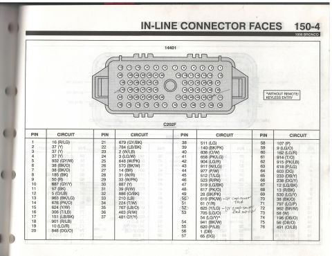
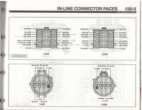
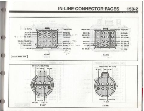
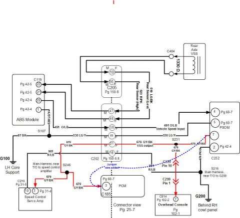
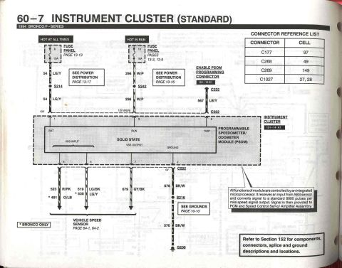
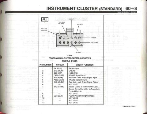
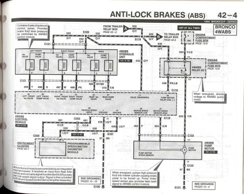
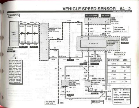
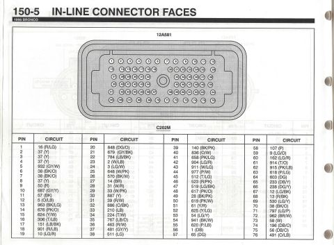
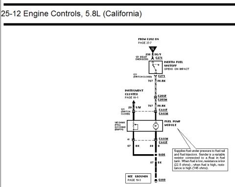
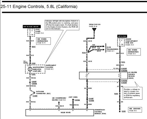








Manual page showing E4OD transmission connector pinout with wire color codes and circuit functions per pin.
Part of 1992-1996 Ford Bronco Wiring Diagrams
This document is page 30-3 from a 1995 Ford Bronco wiring reference, covering the E4OD automatic transmission connector. It shows a pinout diagram of connector C1048, a gray 12-pin connector at the E4OD transmission, with a physical drawing of the connector face showing pin locations (pins 1-6 on the bottom row, pins 7-12 on the top row) and the wire circuit numbers/colors attached to each terminal. A table below the diagram lists each pin, its circuit number and wire color, and its function: Pin 1 (361, Red) Power from PCM Relay; Pin 2 (315, Pink/Orange) Shift Solenoid #2 Output; Pin 3 (237, Orange/Yellow) Shift Solenoid #1 Output; Pin 4 (480, Pink/Yellow) Torque Converter Clutch Control Solenoid; Pin 5 (924, Brown/Orange) Coast Clutch Solenoid; Pin 7 (923, Orange/Black) Transmission Fluid Temperature Sensor; Pin 8 (359, Gray/Red) Sensor Signal Return; Pin 11 (925, White/Yellow) Electronic Pressure Control; Pin 12 (361, Red) Electronic Pressure Control Power. Pins 6, 9, and 10 are not used. This page is useful for diagnosing E4OD electrical faults, solenoid pack wiring, and harness repairs.
Is this accurate? Sign in to help verify it.
Frequently asked questions
- What is the connector number for the E4OD transmission on a 1995 Ford Bronco?
- The connector is C1048, a gray 12-pin connector at the E4OD transmission.
- Which pin on the E4OD connector controls the torque converter clutch?
- Pin 4, circuit 480 (Pink/Yellow), is the Torque Converter Clutch Control Solenoid.
- Which pins carry the shift solenoid signals?
- Pin 2, circuit 315 (P/O), is Shift Solenoid #2 Output, and Pin 3, circuit 237 (O/Y), is Shift Solenoid #1 Output.
- What wire is used for the transmission fluid temperature sensor?
- Pin 7, circuit 923 (Orange/Black), is the Transmission Fluid Temperature Sensor; its return is Pin 8, circuit 359 (GY/R), Sensor Signal Return.
- Which pins on the E4OD C1048 connector are not used?
- Pins 6, 9, and 10 are marked NOT USED.






No comments yet.