Home/
Registry/
Ford/
Bronco/
1987-1991/
1988 Ford Bronco/
Photo
supermotors.net/registry/media/1017245
Ford Bronco/F-Series A/C-Heater Electrical Wiring Diagram - Clutch Circuit
Reference · 1987-1991 BroncoAll 175 wiring diagrams




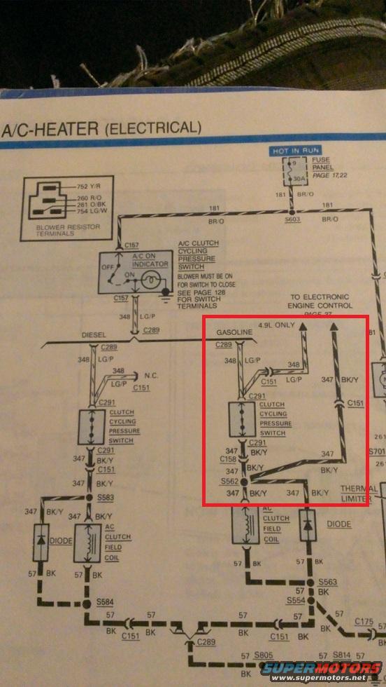
A/C-heater electrical wiring diagram showing the clutch cycling pressure switch, blower resistor and color-coded circuits.
Part of 1987-1991 Ford Bronco Wiring Diagrams
This is a scanned page from a Ford factory-style electrical/vacuum troubleshooting manual (EVTM) showing the A/C-Heater (Electrical) wiring diagram. It covers the A/C clutch circuit fed from fuse panel position 9 (30 amp, hot in run) through circuit 181 (BR/O wire) and splice S603 to the A/C ON indicator switch at connector C157. From there, circuit 348 (LG/P) splits into two branches at connector C289: a DIESEL branch and a GASOLINE branch (highlighted with a red box by the uploader). Each branch passes through a clutch cycling pressure switch (connector C291), then circuit 347 (BK/Y) to the A/C clutch field coil and a suppression diode, returning to ground on circuit 57 (BK) through splices S583/S584 (diesel) and S562/S563/S554 (gasoline). A note indicates a lead "TO ELECTRONIC ENGINE CONTROL PAGE 37" applies to the 4.9L engine only, and the gasoline side also shows a thermal limiter. Legend text identifies blower resistor terminal circuits 752 Y/R, 260 R/O, 261 O/BK, and 754 LG/W. A caution states the blower must be on for the switch to close, referencing page 128 for switch terminals. Connectors and splices shown include C151, C157, C158, C175, C289, C291, S562, S583, S584, S603, S805, and S814.
Is this accurate? Sign in to help verify it.
Frequently asked questions
- What fuse powers the A/C clutch circuit in this diagram?
- Fuse panel position 9, a 30A fuse that is hot in run (fuse panel details on pages 17 and 22), feeding circuit 181 (BR/O wire).
- What wire colors are used for the A/C clutch cycling pressure switch circuits?
- Circuit 348 is LG/P (light green/purple) into the clutch cycling pressure switch, and circuit 347 is BK/Y (black/yellow) out of it to the A/C clutch field coil. Ground is circuit 57 (BK).
- What are the blower resistor terminal wire colors?
- The legend shows circuit 752 Y/R, circuit 260 R/O, circuit 261 O/BK, and circuit 754 LG/W.
- Does the diagram differ between diesel and gasoline engines?
- Yes. Circuit 348 splits at C289 into separate DIESEL and GASOLINE branches, each with its own clutch cycling pressure switch (C291), diode, and A/C clutch field coil. The gasoline side also includes a thermal limiter and a 4.9L-only feed to the Electronic Engine Control (page 37).
- Is there any condition required for the A/C clutch cycling pressure switch to close?
- Yes: a note states the blower must be on for the switch to close, and refers to page 128 for switch terminal details.






No comments yet.