SuperMotors SuperMotors SUPERMOTORS Search: try “orange Bronco on 35s”
Home/ Registry/ Ford/ Bronco/ 1987-1991/ 1988 Ford Bronco/ Photo supermotors.net/registry/media/1023752

Manual steps 34-36 for checking TPS reference voltage and resist…

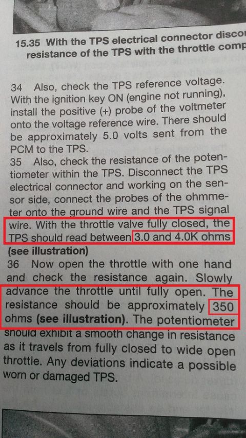
Manual steps 34-36 for checking TPS reference voltage and resistance with highlighted ohm specs
Manual steps 34-36 for checking TPS reference voltage and resistance with highlighted ohm specsOriginal file
Manual steps 34-36 for checking TPS reference voltage and resistance with highlighted ohm specs

Reference · 1987-1991 BroncoAll 95 service procedures
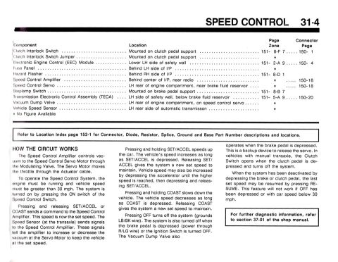
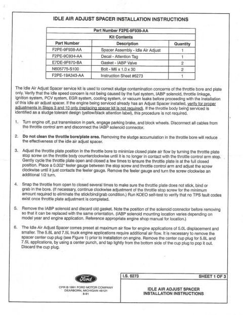
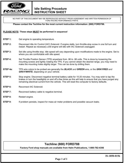
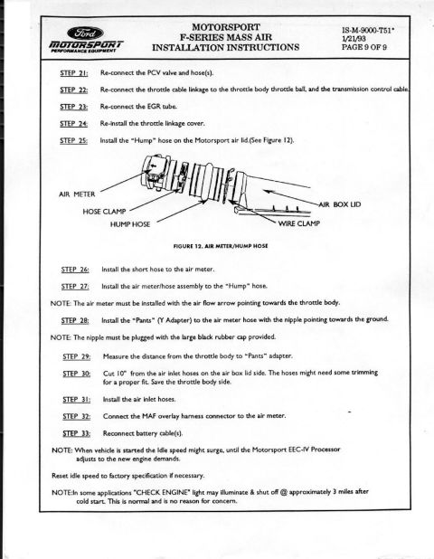
Manual steps 34-36 for checking TPS reference voltage and resistance with highlighted ohm specs Ford Canister Purge Regulator Valve (CANP 9C915) Test Procedure - Figure 11 1990 Ford Speed Control 31-4: Cruise Control Component Locations & Operation Idle Air Adjust Spacer instruction for removing the center cup plug on 5.8L and 7.5L truck engines Ford Idle Air Adjust Spacer Installation Instructions F2PE-9F939-AA (Sheet 1/3) Ford Racing Idle Setting Procedure & TPS Adjustment Instruction Sheet IS-1850-0156 Ford Motorsport F-Series Mass Air MAF Install Instructions Page 9 - Final Steps Ford Motorsport F-Series Mass Air Conversion Instructions - Page 8 of 9 (M-9000-T51) Ford Motorsport F-Series Mass Air Install Instructions Page 7 - EEC-IV Swap Ford Motorsport F-Series Mass Air Install Page 6 - EEC-IV Removal 1987-1992 Ford Motorsport F-Series Mass Air Install Instructions Page 5 - Intake Removal Ford Motorsport F-Series Mass Air Install Instructions Page 4 - EGR & Vacuum 95service procedures1987-1991 Ford Bronco More reference Ford Bronco/F-Series A/C-Heater Electrical Wiring Diagram - Clutch CircuitWiring diagram Ford 5.0 Fox Mustang Short Belt Routing Diagram - 84.5" & 70.5" vs StockSchematic Welder Input Data Plate - Serial JH229505, Stock 901782, 200/230/460V SpecsSpec plate Ford 5.0L V8 PCV Valve & Hose Routing Diagram - 9A474, 6B890, 6A664Exploded parts Ford 5.0L/5.8L Air Throttle Body Assembly Diagram - Canister Purge Ports & TPSManual page Magnum Metropolitan Brochure - Ford Bronco/F-Series Suburban-Style ConversionBrochure Tubing Adapter Blueprint 2.00" OD x 1.375" ID x 3" - 1.125"-12 TPI RH ThreadBlueprint '89 Ford vehicle emission control information label with EEC IV/EFI timing steps and vacuum hose routingVacuum routing 1990 Ford Bronco Fuse Panel Diagram: Fuse Positions, Amps & Circuits (11-2)Fuse chart Ford V8 Intake Manifold Bolt Tightening Sequence Diagram - Stud LocationsTorque spec

TPS test procedure: about 5.0 volts reference from the PCM, 3.0 to 4.0K ohms with throttle closed, and about 350 ohms at wide open throttle.

Part of 1987-1991 Ford Bronco Service Procedures

AI caption · Photo 68 of 68

15.35 With the TPs electrical connector discm resistance of the TPS with the throttle com: 34 Also, check the TPS reference voltege. With the ignition key ON (engine not running), install the positive (+) probe of the voltmeter onto the voltage reference wire. There should be approximately 5.0 volts sent from the PCM to the TPS. 35 Also check the resistance of the poten- tiometer within the TPS. Disconnect the TPS electrical connector and working on the sen sor side, connect the probes of the ohmme ter onto the round wire and the TPS signal (see illustration) 36 Now open the throttle with one hand and check the resistance again. Slowl resistance should be approximately ohm llgstration) In a

Is this accurate? Sign in to help verify it.

Comments

No comments yet.

More 1987-1991 Broncos