SuperMotors SuperMotors SUPERMOTORS Search: try “orange Bronco on 35s”
Home/ Registry/ Ford/ Bronco/ 1992-1996/ “JUICE”/ Photo supermotors.net/registry/media/1068854

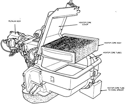
Ford Bronco Heater Core & Plenum Assembly Diagram - Core, Cover, Tubes
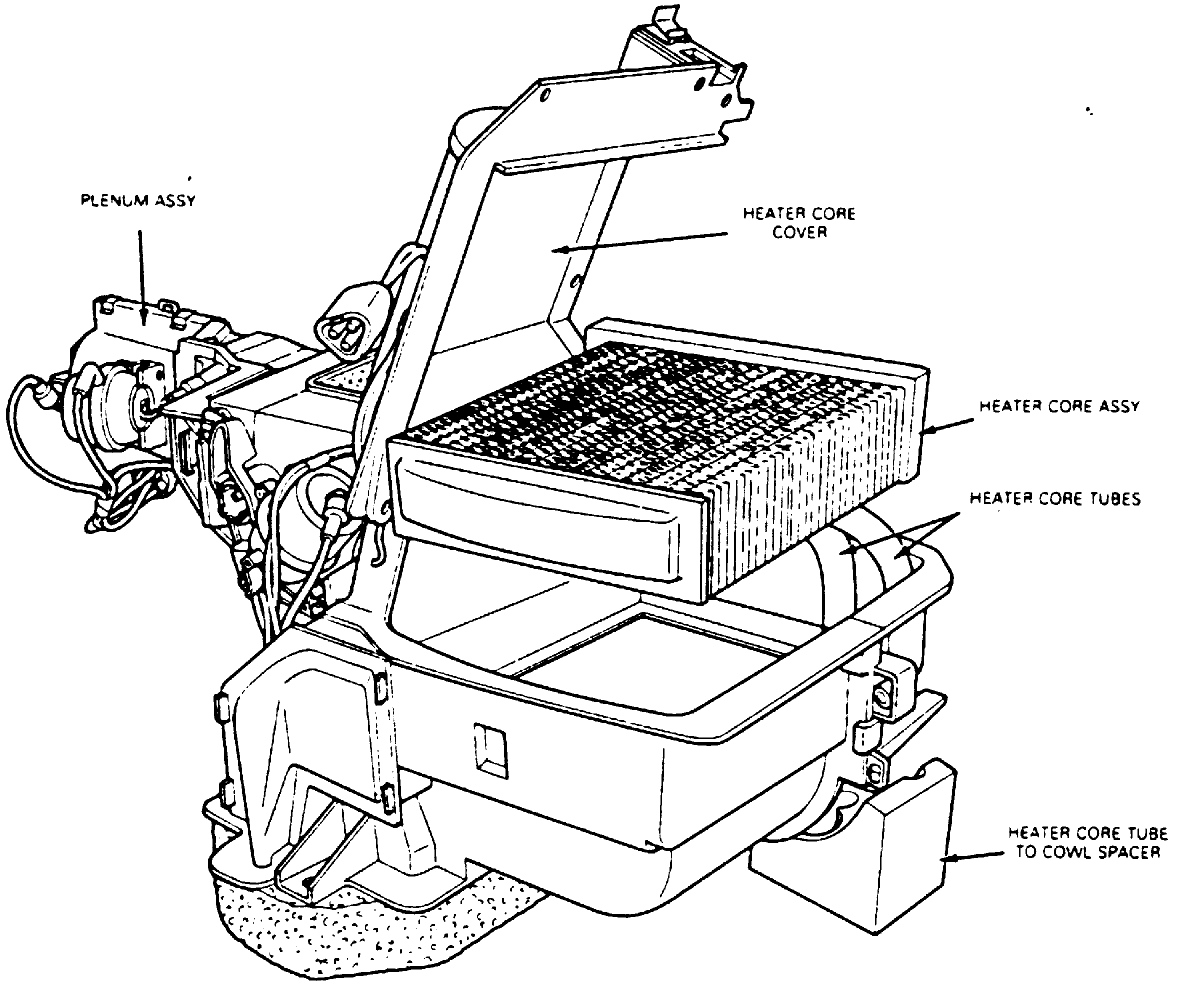
Exploded assembly drawing of heater core, plenum, cover, and core tubes
Exploded assembly drawing of heater core, plenum, cover, and core tubesOriginal file
Exploded assembly drawing of heater core, plenum, cover, and core tubes

Reference · 1992-1996 BroncoAll 169 exploded parts diagrams

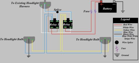
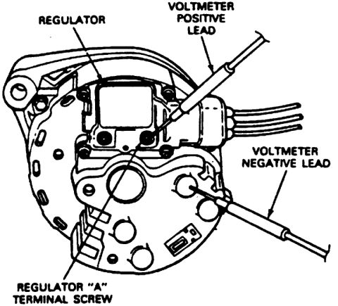
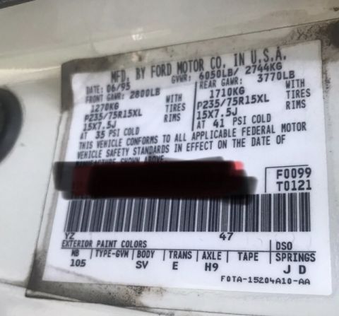
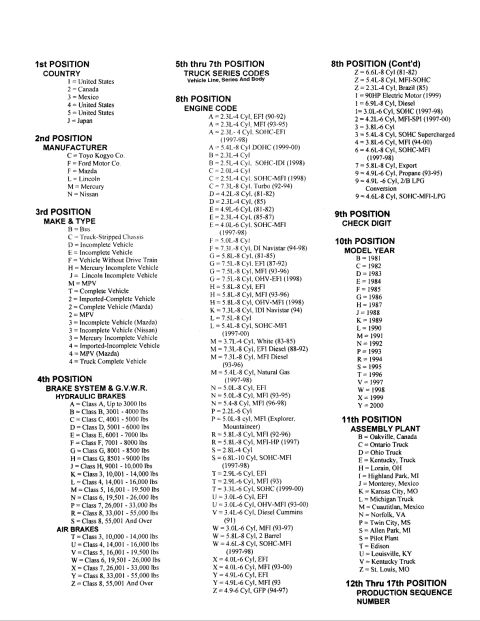
Ford F-150 & Bronco Automatic Locking Hub Exploded Diagram (E9804-A) Ford Bronco Front Wheel Bearing & Hub Exploded Diagram with Torque Specs Ford Bronco/F-150 4x4 Front Hub & Wheel Bearing Exploded Diagram w/ Torque Specs Ford Bronco Front Wheel Hub & Bearing Exploded Diagram - Torque Specs Ford Oil Pan Gasket 6710 Installation Diagram - Sealer Points WSE-M4G323-A3 Ford Bronco Heater Core & Plenum Assembly Diagram - Core, Cover, Tubes Ford Bronco Oil Pan Exploded Diagram - Bolt Torque Specs & Part Numbers Ford Vacuum Control Solenoid Assembly Diagram - E8AE-9H465-BA & E8AE-9H485-AA 1996 Ford Bronco/F-150 Distributor Exploded Parts Diagram & Installation 03-07A-6 Ford Bronco Front Coil Spring & Shock Absorber Exploded Diagram (F2858-Q) Ford Bronco/F-Series Engine Block Ground Cable Diagram - Neg Battery Cable Views Instrument panel 04320 exploded view with finish panel 044D70, headlamp switch knob 11666 and mouldings 169exploded parts diagrams1992-1996 Ford Bronco More reference Headlight Relay Wiring Diagram - Dual Relay Harness Upgrade (Ford Bronco)Wiring diagram Ford Alternator Voltage Regulator Test Diagram - Voltmeter Lead PlacementService procedure 1995 Ford Bronco Door Jamb Data Plate - GVWR, Tire Pressure & Axle CodesSpec plate Ford truck VIN decoder chart explaining positions 1 through 17, engine codes, model years and plantsManual page Caster Angle Diagram - Ford Solid Axle Radius Arm & C-Bushing Steering GeometrySchematic Line graph of percentage change in Bronco values, 2008 to 2018, for four Ford Bronco generationsBrochure Ford Bronco A/C-Heater Vacuum Diagram - HVAC Vacuum Line Routing & Door MotorsVacuum routing Brake Booster to Master Cylinder Adapter Plate Blueprint - Ford Bronco SwapBlueprint Ford Bronco/F-Series Fuse 18 (10A) - Speedometer, Air Bag, Shift ControlFuse chart Rod Bolt Stretch Monitoring Chart - 8-Rod V8 Connecting Rod Bolt Record SheetTorque spec

Exploded assembly drawing of the heater core, plenum assembly, core cover, and heater core tubes.

Part of 1992-1996 Ford Bronco Exploded Parts Diagrams

AI caption · Photo 101 of 561

This document is a black-and-white exploded/cutaway line drawing of a heater plenum assembly, uploaded to a 1995 Ford Bronco gallery. It illustrates the heater core installation within the HVAC plenum box. Five components are labeled with callout arrows: the plenum assembly (the main housing on the left, shown with attached vacuum lines, actuators, and wiring), the heater core cover (shown lifted/opened upward to expose the core), the heater core assembly (the finned rectangular core shown partially removed from its cavity), the heater core tubes (the two inlet/outlet tubes exiting the side of the core), and the heater core tube to cowl spacer (a block-shaped spacer piece at the lower right where the tubes pass through the cowl). The drawing gives a reader a clear visual reference for how the heater core seats inside the plenum, how the cover is oriented over it, and where the tube-to-cowl spacer fits, useful when replacing a leaking heater core or reassembling the plenum. The document contains no part numbers, torque specifications, model years, or written procedures; it is purely an identification/orientation illustration.

Is this accurate? Sign in to help verify it.

Frequently asked questions

What components are labeled in this heater diagram?
The diagram labels the plenum assembly, heater core cover, heater core assembly, heater core tubes, and the heater core tube to cowl spacer.
Where is the heater core located according to this diagram?
The heater core assembly sits inside the plenum assembly, beneath the heater core cover, which is shown lifted open to expose the core.
What is the part shown at the lower right of the drawing?
It is the heater core tube to cowl spacer, positioned where the heater core tubes pass toward the cowl.
Does this document include torque specs or part numbers?
No. It is an exploded illustration with component labels only; no part numbers, torque values, or written instructions are shown.


Comments

No comments yet.

More 1992-1996 Broncos