Ford Bronco 5.8L Secondary Air (Thermactor) System Exploded Parts Diagram

Reference · 1987-1991 BroncoAll 61 exploded parts diagrams
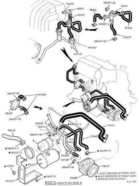
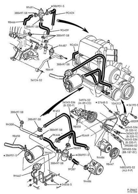
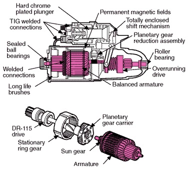
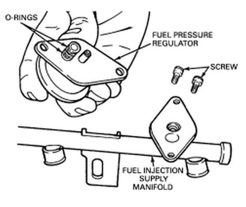
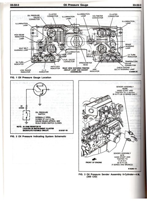
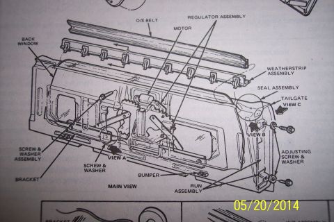
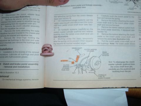
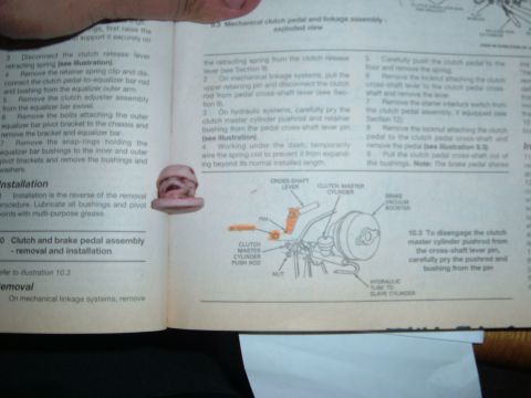
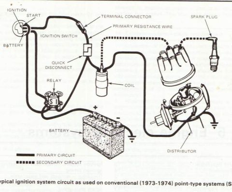








Exploded parts diagram of the thermactor air-injection plumbing showing valves, hoses, air pump and Ford part numbers across two pages.
Part of 1987-1991 Ford Bronco Exploded Parts Diagrams
This document is a Ford factory-style exploded parts illustration (drawing number P-21187, marked 'PAGE A, CONT'D ON PAGE B') showing the secondary air injection (Thermactor) system hose routing and component layout, uploaded as applying to a 1990 Ford Bronco with the 5.8L engine. The drawing presents three views: an upper detail of the air control/bypass valve assembly with associated hoses and clamps (callouts 9A474, 68890, 6A664, 9F491, 9B466, 9K466, 9G459, 9A487, 5F235, clamp 388497-S8, and 390007-S), a small inset of a check valve/hose assembly (9B289, 9H300), and a main lower view of the engine showing the air pump (9A486), pump pulley area (9B447), hoses and tubes (9F451, 9S449, 9J435, 9F287, 9B458), mounting bracket (9H467), solenoid/canister components (9G427), and various clamps and fasteners (386951-S, 383527-S, 38374-S, 45334, 34657-S). Footnotes indicate which parts are also serviced within the 9H300 or 9H467 assemblies. A reader can identify Ford base part numbers for every hose, valve, clamp, and bracket in the secondary air system for parts ordering and correct hose routing.
Is this accurate? Sign in to help verify it.
Frequently asked questions
- What part number is the secondary air pump in this diagram?
- The air pump is called out as 9A486, with 9B447 shown adjacent to it on the pump assembly.
- Which clamp part number is used repeatedly on the hoses?
- Clamp 388497-S8 appears at multiple hose connections throughout the diagram.
- Which parts are serviced only as part of another assembly?
- Per the footnotes: parts marked % are also serviced in the 9H300 assembly, parts marked ▲ are also serviced in the 9H467 assembly, and parts marked # are serviced only in 9H467.
- Is this the complete diagram?
- No: it is labeled 'PAGE A, CONT'D ON PAGE B', so a second page continues the illustration.
- What are the hose part numbers shown in the lower engine view?
- Hoses/tubes called out include 9F451, 9S449, 9J435, 9F287, 9B458, and 9H300.






No comments yet.