Ford Bronco Starter & Fender Apron Relay Diagnosis - Pinpoint Test Chart

Reference · 1992-1996 BroncoAll 142 service procedures
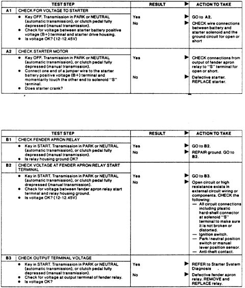
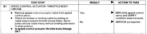




Ford starting-system pinpoint test chart (steps A1-A2, B1-B3) for checking voltage to starter, starter motor, and fender apron relay; specifies 12-12.45V as the OK voltage threshold.
Part of 1992-1996 Ford Bronco Service Procedures
This document is a starter system diagnostic pinpoint test chart, laid out in the standard Ford shop-manual format with columns for Test Step, Result, and Action to Take. It contains two test sequences. Test A (steps A1-A2) checks for voltage to the starter: A1 verifies battery voltage (12-12.45V) between the starter B+ terminal and the starter drive housing with the key off; A2 uses a jumper wire from the B+ terminal to the solenoid "S" terminal to see if the starter cranks, with a failed test indicating a defective starter that should be replaced. Test B (steps B1-B3) diagnoses the fender apron (starter) relay: B1 checks the relay housing ground, B2 checks voltage at the relay start terminal with the key in START (failure points to open circuits, the ignition switch, park/neutral position switch or manual lever position sensor, or anti-theft contact), and B3 checks voltage at the relay output terminal, with failure indicating a defective fender apron relay to be removed and replaced. Each step notes the transmission should be in PARK or NEUTRAL (automatic) or the clutch pedal fully depressed (manual). A reader can use this chart to systematically isolate no-crank problems to wiring, the relay, or the starter motor.
Is this accurate? Sign in to help verify it.
Frequently asked questions
- What voltage should be present at the starter B+ terminal?
- 12 to 12.45 volts, measured between the starter battery positive voltage (B+) terminal and the starter drive housing with the key OFF.
- How do I test if the starter motor itself is bad?
- With the key OFF and the transmission in PARK or NEUTRAL (or clutch fully depressed on a manual), connect a jumper wire from the starter B+ terminal and momentarily touch it to the solenoid "S" terminal. If the starter does not crank, the starter is defective and should be replaced.
- What should I check if there is no voltage at the fender apron relay start terminal?
- Check for an open circuit or high resistance in the external wiring or components: all circuit connections including the plastic hard-shell connector at the solenoid "S" terminal, the ignition switch, the park/neutral position switch or manual lever position sensor, and the anti-theft contact.
- What does it mean if there is no voltage at the fender relay output terminal in step B3?
- The fender apron relay is defective, remove and replace the relay.
- What vehicle setup is required before running these starter tests?
- The transmission must be in PARK or NEUTRAL for automatic transmissions, or the clutch pedal fully depressed for manual transmissions; key OFF for Test A and key in START for Test B.






No comments yet.