SuperMotors SuperMotors SUPERMOTORS Search: try “orange Bronco on 35s”
Home/ Registry/ Ford/ Bronco/ 1992-1996/ “JUICE”/ Photo supermotors.net/registry/media/904843

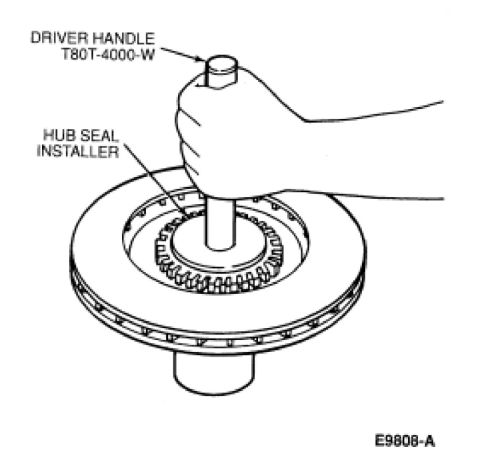
Ford Bronco Front Hub Seal Installation - Driver Handle T80T-4000-W Diagram
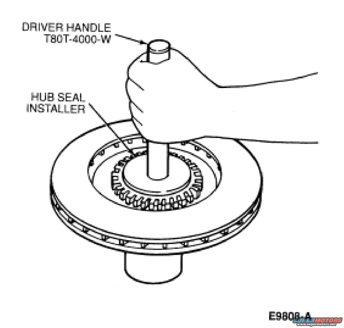
Illustration of hub seal installer and driver handle seating a seal in the hub
Illustration of hub seal installer and driver handle seating a seal in the hubOriginal file
Illustration of hub seal installer and driver handle seating a seal in the hub

Reference · 1992-1996 BroncoAll 143 service procedures
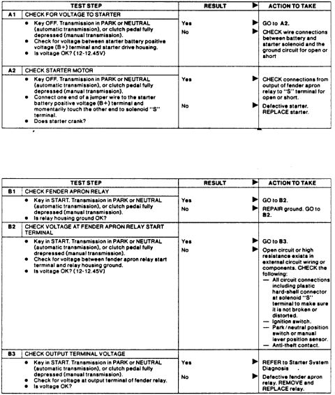
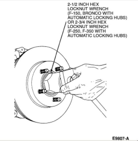
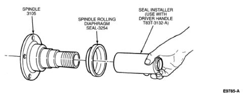
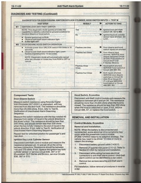
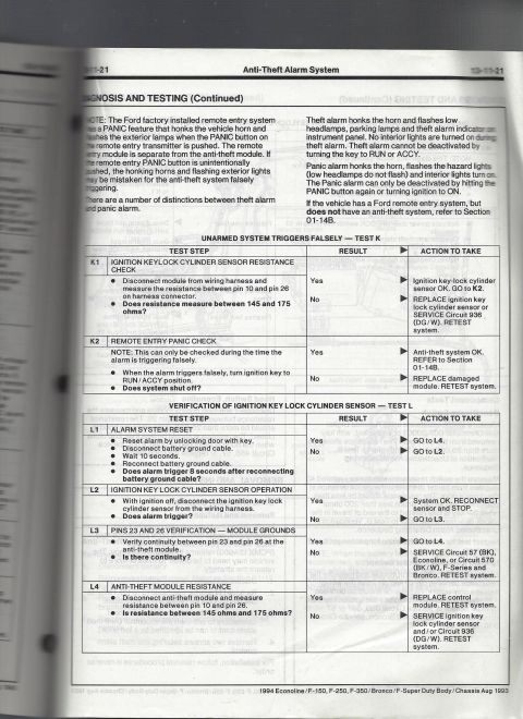
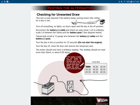
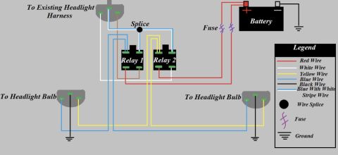
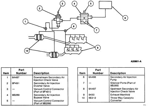
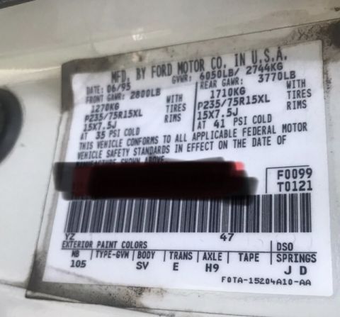
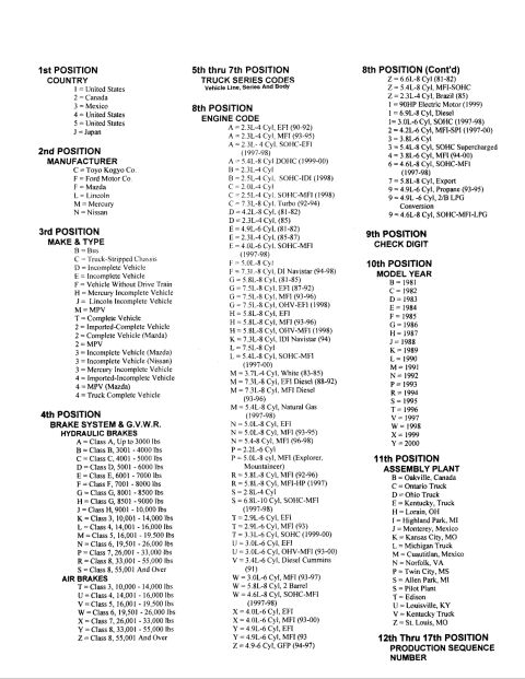
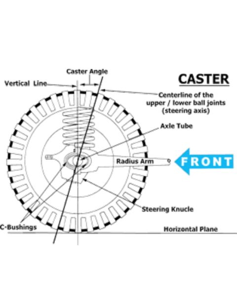
Ford Alternator Voltage Regulator Test Diagram - Voltmeter Lead Placement Ford Bronco Starter & Fender Apron Relay Diagnosis - Pinpoint Test Chart Ford Bronco F-150 F-250 F-350 Front Hub Locknut Wrench - Bearing Service Diagram Ford Bronco Front Hub Seal Installation - Driver Handle T80T-4000-W Diagram Ford Front Spindle Rolling Diaphragm Seal 3254 Installation - Tool T83T-3132-A Ford Bronco F-150 F-250 F-350 Hub Locknut Wrench T83T-1197-B Bearing Service Ford Bronco F-150 F-250 F-350 Front Hub Locknut Wrench Diagram (E9807-A) Test step B1 chart for speed control actuator and throttle body linkage Ford F150/F250/F350 4x4 & Bronco Truck Jacking Instructions Label E7TA-17A083-EA 1994 Ford Bronco/F-150/Econoline Anti-Theft Alarm Diagnosis Test M (13-11-22) 1994 Ford Bronco/F-150 Anti-Theft Alarm Diagnosis - Tests K & L (13-11-21) Parasitic Battery Draw Test Procedure - Checking for Unwanted Draw (Wilson) 143service procedures1992-1996 Ford Bronco More reference Headlight Relay Wiring Diagram - Dual Relay Harness Upgrade (Ford Bronco)Wiring diagram Ford Bronco Secondary Air Injection System Diagram - Smog Pump Parts & LayoutExploded parts 1995 Ford Bronco Door Jamb Data Plate - GVWR, Tire Pressure & Axle CodesSpec plate Ford truck VIN decoder chart explaining positions 1 through 17, engine codes, model years and plantsManual page Caster Angle Diagram - Ford Solid Axle Radius Arm & C-Bushing Steering GeometrySchematic Line graph of percentage change in Bronco values, 2008 to 2018, for four Ford Bronco generationsBrochure Ford Bronco A/C-Heater Vacuum Diagram - HVAC Vacuum Line Routing & Door MotorsVacuum routing Brake Booster to Master Cylinder Adapter Plate Blueprint - Ford Bronco SwapBlueprint Ford Bronco/F-Series Fuse 18 (10A) - Speedometer, Air Bag, Shift ControlFuse chart Rod Bolt Stretch Monitoring Chart - 8-Rod V8 Connecting Rod Bolt Record SheetTorque spec

Service illustration showing the hub seal installer and driver handle T80T-4000-W seating the seal in the disc brake hub.

Part of 1992-1996 Ford Bronco Service Procedures

AI caption · Photo 70 of 561

This document is a single line-art service illustration showing the installation of a front hub seal using Ford special service tools. The drawing depicts a hand holding a Driver Handle (Ford tool number T80T-4000-W) with a Hub Seal Installer attached, positioned in the center bore of a front hub/rotor assembly (a vented disc brake rotor with an internal-gear/lock ring visible in the hub). Callout arrows identify the two tools: the driver handle at the top and the hub seal installer where the tool meets the seal bore. The figure is identified by illustration code E9808-A in the lower right corner. A reader can learn which special tools are specified for driving a new hub seal squarely into the hub of the rotor assembly and how the tools are oriented during installation. The illustration contains no text beyond the tool labels and figure number, no torque specifications, no year/model applicability statement, and no written procedure steps. It appears to be one page (bearing5.jpg) of a multi-page front wheel bearing/hub service procedure set uploaded for a 1995 Ford Bronco.

Is this accurate? Sign in to help verify it.

Frequently asked questions

What tool is used to install the hub seal?
The diagram shows a Hub Seal Installer used together with Driver Handle T80T-4000-W.
What is the Ford tool number for the driver handle?
The driver handle is labeled T80T-4000-W.
How is the hub seal installed according to this diagram?
The hub seal installer is placed in the center of the hub/rotor assembly and driven with the T80T-4000-W driver handle held by hand.
What is the figure or illustration number of this diagram?
The illustration is identified as E9808-A.

Comments

No comments yet.

More 1992-1996 Broncos