Home/
Registry/
Ford/
Bronco/
1992-1996/
1996 Ford Bronco/
Photo
supermotors.net/registry/media/892363
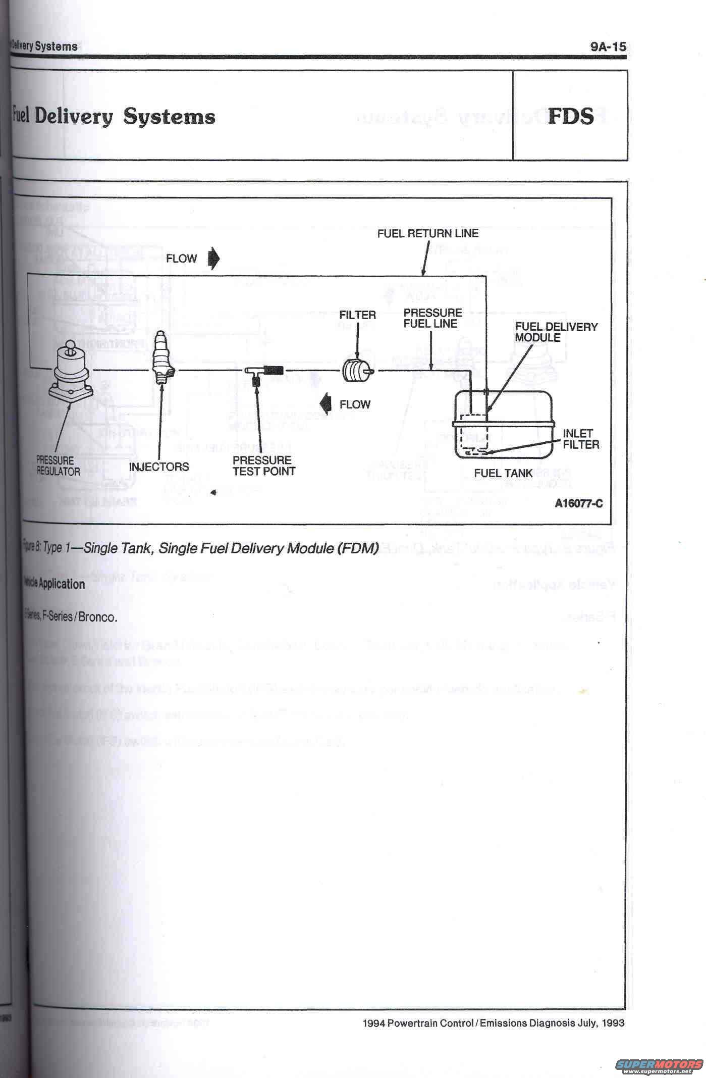
1994 Ford Bronco/F-Series Fuel Delivery System Diagram - Single Tank FDM
Reference · 1992-1996 BroncoAll 95 schematics
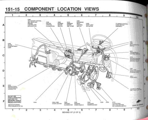


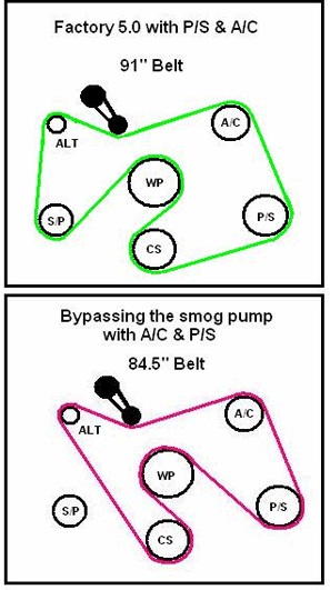
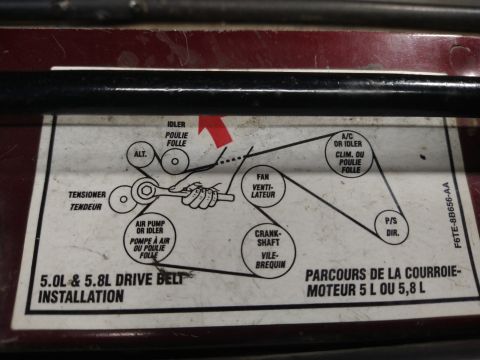
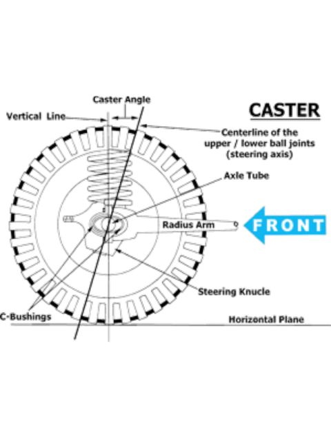






Schematic of a single-tank fuel delivery module showing flow through the regulator, injectors, filter and fuel tank.
Part of 1992-1996 Ford Bronco Schematics
This is page 9A-15 from the Ford 1994 Powertrain Control / Emissions Diagnosis manual (dated July 1993), in the Fuel Delivery Systems (FDS) section. The page presents Figure 8: 'Type 1: Single Tank, Single Fuel Delivery Module (FDM),' a schematic diagram of the fuel delivery system layout. The diagram (reference number A16077-C) traces fuel flow from the fuel tank, containing the fuel delivery module and inlet filter, through the pressure fuel line and inline filter, past a pressure test point, to the fuel injectors and pressure regulator, with a fuel return line routing excess fuel back to the tank. Flow direction arrows indicate fuel movement in both the supply and return paths. The vehicle application section states this Type 1 configuration applies to E-Series, F-Series, and Bronco vehicles. A reader can learn the overall architecture of the single-tank Ford truck fuel system, the sequence of components in the fuel path, and where the pressure test point is located relative to the injectors and filter, useful for fuel pressure diagnosis. Some ghosted text from the reverse side of the page and faded paragraphs below the vehicle application line are not legible.
Is this accurate? Sign in to help verify it.
Frequently asked questions
- What does this diagram show?
- Figure 8 shows the Type 1 fuel delivery system: a single tank with a single Fuel Delivery Module (FDM), including the fuel tank, inlet filter, pressure fuel line, inline filter, pressure test point, injectors, pressure regulator, and fuel return line.
- Which vehicles does this Type 1 single-tank fuel system apply to?
- The Vehicle Application section lists E-Series, F-Series / Bronco.
- Where is the fuel pressure test point located?
- Per the diagram, the pressure test point is on the fuel line between the inline filter and the injectors.
- What components are inside the fuel tank in this system?
- The fuel delivery module and its inlet filter are shown inside the fuel tank.
- What manual is this page from?
- Page 9A-15 of the 1994 Powertrain Control / Emissions Diagnosis manual, dated July 1993.






No comments yet.