Home/
Registry/
Ford/
Bronco/
1978-1979/
“buyers guide”/
Photo
supermotors.net/registry/media/975553
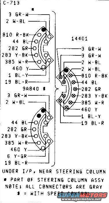
1979 Ford Bronco Turn Signal Switch Connector C-713 Pinout & Wire Colors
Reference · 1978-1979 BroncoAll 116 wiring diagrams
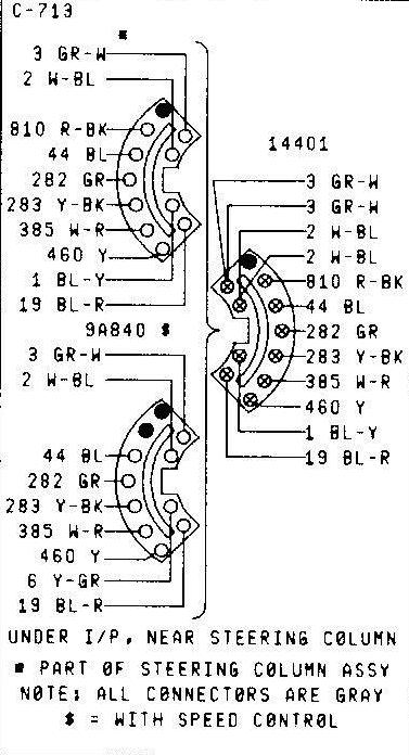
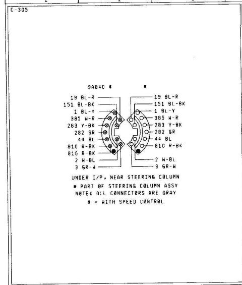
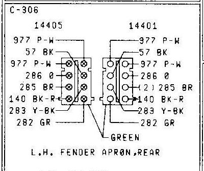
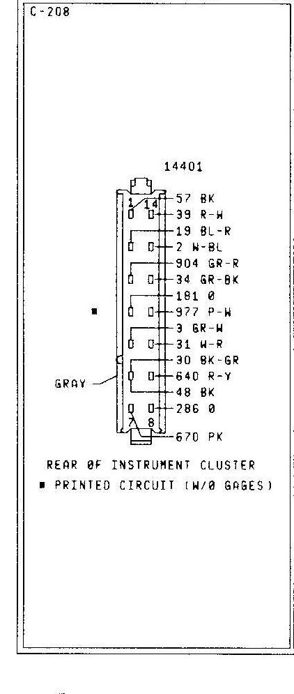
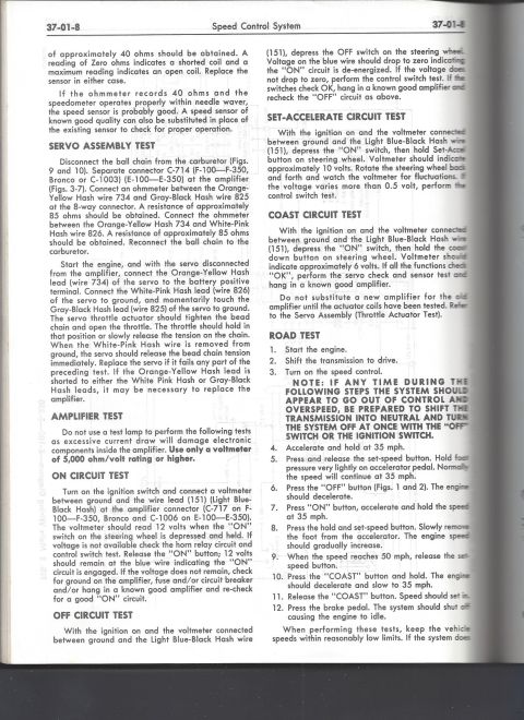
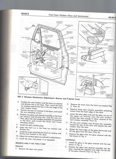
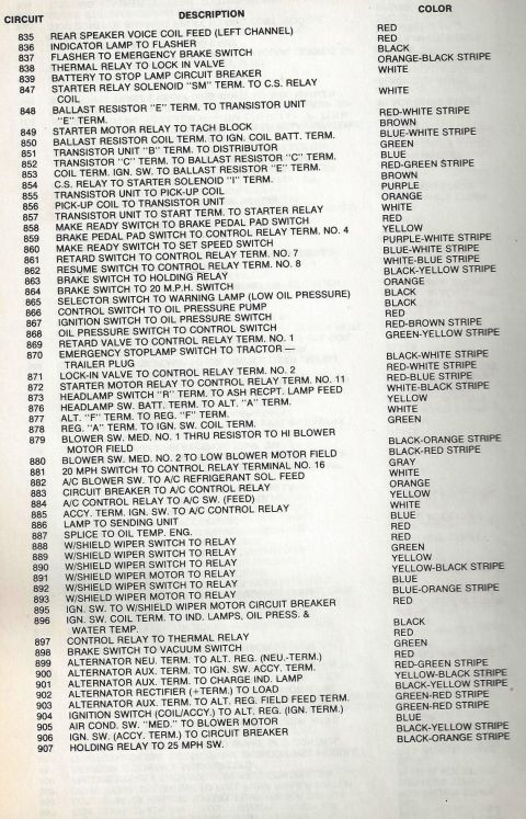


Wiring connector diagram for steering column assembly (C-713) under I/P with speed control, listing pin wire numbers and colors.
Part of 1978-1979 Ford Bronco Wiring Diagrams
This document is a connector pinout diagram for a Ford turn signal switch connection, identified as connector C-713, located under the instrument panel near the steering column. It shows three half-moon (semi-circular) connector faces: two on the left side that are part of the steering column assembly (one applies to vehicles with speed control, associated with harness 9A840), and one mating connector on the right belonging to the main wiring harness (14401). Each connector pin is labeled with its circuit number and wire color code: 3 GR-W (green-white), 2 W-BL (white-blue), 810 R-BK (red-black), 44 BL (blue), 282 GR (green), 283 Y-BK (yellow-black), 385 W-R (white-red), 460 Y (yellow), 1 BL-Y (blue-yellow), 19 BL-R (blue-red), and 6 Y-GR (yellow-green, on the speed control variant). Footnotes state that the connector is located under the I/P near the steering column, that the marked connector is part of the steering column assembly, that all connectors are gray, and that the '$' symbol denotes wiring used with speed control. This diagram is useful for identifying wires when repairing or replacing a turn signal switch or diagnosing turn signal, brake light, hazard, or speed control circuit issues.
Is this accurate? Sign in to help verify it.
Frequently asked questions
- Where is the turn signal switch connector C-713 located?
- According to the diagram, it is located under the instrument panel (I/P), near the steering column.
- What wire colors are used at the turn signal switch connector?
- The circuits and colors shown are: 3 GR-W (green-white), 2 W-BL (white-blue), 810 R-BK (red-black), 44 BL (blue), 282 GR (green), 283 Y-BK (yellow-black), 385 W-R (white-red), 460 Y (yellow), 1 BL-Y (blue-yellow), 19 BL-R (blue-red), and 6 Y-GR (yellow-green) on the speed control version.
- What does the '$' symbol mean on this diagram?
- The legend states '$ = WITH SPEED CONTROL', meaning that connector variant applies to vehicles equipped with speed control.
- What color are the connectors?
- A note on the diagram states that all connectors are gray.
- Which connector is part of the steering column assembly?
- The connector marked with the asterisk/square symbol is noted as 'PART OF STEERING COLUMN ASSY'.






No comments yet.