Home/
Registry/
Ford/
Bronco/
1992-1996/
1996 Ford Bronco/
Photo
supermotors.net/registry/media/1137465
1996 Ford Bronco Trailer/Camper Adapter Wiring Diagram - EVTM Page 95-2
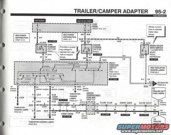
Wiring diagram of the trailer/camper adapter showing turn/hazard flashers and stop/turn lamp circuits (page 95-2).
This is page 95-2 of the 1996 Ford Bronco Electrical and Vacuum Troubleshooting Manual (EVTM), showing the second sheet of the Trailer/Camper Adapter wiring diagram. It traces the turn signal and hazard flasher circuits feeding the trailer wiring. Power comes from fuse 7 (15A, hot in run) through circuit 8 O/Y to the turn flasher on the fuse panel, and from fuse 13 (15A, hot at all times) through circuit 383 R/W to the hazard flasher. Flasher outputs (44 LB and 385 W/R) feed the multi-function switch (connector C231), which routes signals via circuits 9 LG/O, 5 O/LB, 3 LG/W, and 2 W/LB to the turn/stop/hazard lamps. The brake on/off (BOO) switch (C279) provides circuit 511 LG to operate trailer stop lamps. Circuits 52 Y and 64 DG pass through 10A fuses in the engine compartment fuse box and through connectors C112, C407, and C417 to the trailer left and right turn lamps. Splices S219, S225, S236, and S240 and connectors C202F/M and C205F/M are identified, with cross-references to power distribution (13-7, 13-10), fuse box pages (13-3, 13-7, 13-8), lamp circuits (90-1, 90-2, 90-3), switch testing (149-3), and component location grids (151-x).
Is this accurate? Sign in to help verify it.
Frequently asked questions
- What fuses power the turn signal and hazard flashers on a 1996 Bronco?
- Fuse 7 (15A, hot in run) powers the turn flasher via circuit 8 O/Y, and fuse 13 (15A, hot at all times) powers the hazard flasher via circuit 383 R/W. Both flashers are on the fuse panel.
- What wire colors feed the 1996 Bronco trailer turn lamps?
- Circuit 52 Y (yellow) goes to the trailer left turn lamps and circuit 64 DG (dark green) goes to the trailer right turn lamps, each through a 10A fuse (positions 7 and 6) in the engine compartment fuse box and connectors C112, C407, and C417.
- What circuit does the brake on/off (BOO) switch control for the trailer?
- The BOO switch (connector C279) closes with the brake pedal depressed and allows current flow through circuit 511 LG to operate the trailer stop lamps, continuing to C210 on page 95-3.
- Where is multi-function switch testing covered in the 1996 Bronco EVTM?
- The diagram directs you to page 149-3 for multi-function switch testing; the switch connects via connector C231 at location 151-4 B10.
- Which connectors are in the trailer turn lamp circuits on this diagram?
- C205F/C205M, C202F/C202M, C112M/C112F, C407M/C407F, and C417M/C417F, plus splices S219, S225, S236, and S240.
Comments
More from this build












No comments yet.