Home/
Registry/
Ford/
Bronco/
1992-1996/
1996 Ford Bronco/
Photo
supermotors.net/registry/media/1146282
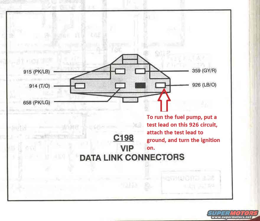
1994 Ford Bronco C198 VIP Data Link Connector Pinout - Fuel Pump Test (926)
Reference · 1992-1996 BroncoAll 411 wiring diagrams
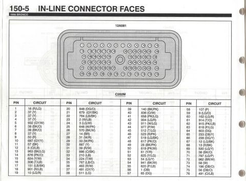
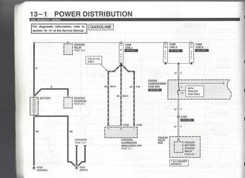
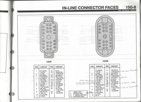
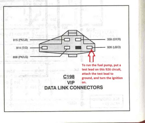







Ford C198 VIP data link connector face pinout with color-coded circuits and note on jumping the 926 circuit to run the fuel pump.
Part of 1992-1996 Ford Bronco Wiring Diagrams
This document is a scanned page from a Ford Electrical and Vacuum Troubleshooting Manual (EVTM) showing connector C198, the VIP (Vehicle In Process / self-test) Data Link Connector. The illustration is a face view of the diagnostic connector with five labeled cavities, each identified by circuit number and wire color code: circuit 915 (pink/light blue), circuit 914 (tan/orange), circuit 658 (pink/light green), circuit 359 (gray/red), and circuit 926 (light blue/orange). A red annotation added by the uploader points to the 926 (LB/O) cavity and explains a practical diagnostic procedure: to run the fuel pump manually, attach a test lead to the 926 circuit, ground the test lead, and turn the ignition on. This grounds the fuel pump relay control circuit through the diagnostic connector, energizing the fuel pump for testing purposes. The page is useful for anyone diagnosing fuel delivery problems, performing EEC-IV self-tests, or identifying the correct pins and wire colors at the underhood data link connector on this era of Ford Bronco/F-Series trucks. The album context identifies it as page 24-12 of a 1994 Bronco EVTM.
Is this accurate? Sign in to help verify it.
Frequently asked questions
- What connector is shown in this diagram?
- Connector C198, the VIP Data Link Connector, shown with its cavity/pin circuit numbers and wire colors.
- What circuits and wire colors are in the C198 VIP data link connector?
- Circuit 915 (PK/LB), 914 (T/O), 658 (PK/LG), 359 (GY/R), and 926 (LB/O).
- How do I run the fuel pump using the data link connector?
- Per the annotation: put a test lead on the 926 (LB/O) circuit at the connector, attach the test lead to ground, and turn the ignition on.
- What wire color is circuit 926 at the VIP connector?
- Circuit 926 is LB/O (light blue with orange).






No comments yet.