Home/
Registry/
Ford/
Bronco/
1992-1996/
1996 Ford Bronco/
Photo
supermotors.net/registry/media/1137466
1996 Ford Bronco Trailer/Camper Adapter Wiring Diagram - EVTM Page 95-3
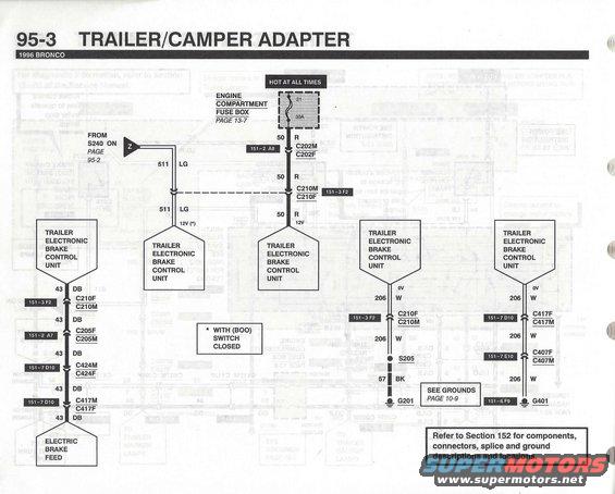
Wiring diagram of the trailer/camper adapter circuit showing electronic brake control units and grounds (page 95-3).
This is page 95-3 of the 1996 Ford Bronco Electrical & Vacuum Troubleshooting Manual (EVTM), the third page of the Trailer/Camper Adapter wiring diagram. It shows the power feed and ground circuits for the Trailer Electronic Brake Control Unit. Battery power comes from fuse 21 (30A) in the engine compartment fuse box (see page 13-7) on circuit 50 (Red), passing through connectors C202M/C202F (151-2 A8) and C210M/C210F (151-3 F2) to the brake control unit. A second feed, circuit 511 (Light Green), comes from splice S240 on page 95-2 and is 12V with the brake on/off (BOO) switch closed. The brake control unit output, circuit 43 (Dark Blue), runs through connectors C210F/C210M, C205F/C205M (151-2 A7), C424M/C424F and C417M/C417F (151-7 D10) to the electric brake feed. Grounds are on circuit 206 (White): one path through C210F/C210M to splice S205 and circuit 57 (Black) to ground G201, the other through C417F/C417M and C407F/C407M (151-7 E10) to ground G401 (151-6 F9, see grounds page 10-9). A note refers readers to Section 152 for component, connector, splice and ground descriptions and locations.
Is this accurate? Sign in to help verify it.
Frequently asked questions
- What fuse powers the trailer electronic brake control unit on a 1996 Bronco?
- Fuse 21, a 30A fuse in the engine compartment fuse box (shown on page 13-7), is hot at all times and feeds circuit 50 (Red) to the trailer electronic brake control unit.
- What wire colors are used in the 1996 Bronco trailer brake controller circuit?
- Circuit 50 is R (red) power, circuit 511 is LG (light green), circuit 43 is DB (dark blue) to the electric brake feed, circuit 206 is W (white) ground, and circuit 57 is BK (black) to ground G201.
- Where does the electric brake feed circuit run on this diagram?
- Circuit 43 (DB) from the trailer electronic brake control unit passes through connectors C210F/C210M, C205F/C205M, C424M/C424F and C417M/C417F to the electric brake feed.
- Where are the grounds for the trailer brake control unit?
- Circuit 206 (W) grounds via splice S205 and circuit 57 (BK) to ground G201, and via connectors C417F/C417M and C407F/C407M to ground G401. See grounds on page 10-9.
- What does the asterisk (*) mean on the 511 LG circuit?
- The 12V notation marked with (*) applies with the BOO (brake on/off) switch closed.
Comments
More from this build












No comments yet.