Home/
Registry/
Ford/
Bronco/
1987-1991/
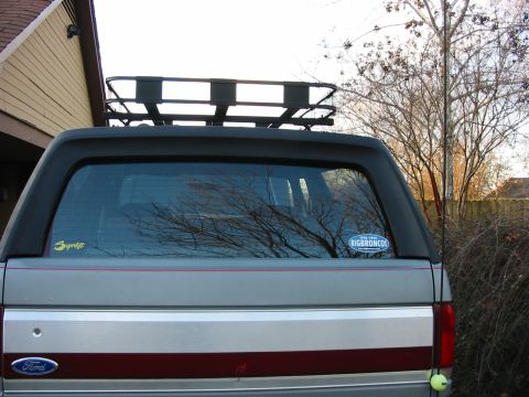
“the magic carpet”/
Photo
supermotors.net/registry/media/777719
14-Bolt Axle Anti-Wrap Traction Bar Design Diagram - Ford Bronco Wrap Bar Idea

Reference · 1987-1991 BroncoAll 112 schematics













Labeled fabrication diagram of a traction-bar setup showing the 14b yoke, plate gussets, S-flex joint, and driveshaft slip splines.
Part of 1987-1991 Ford Bronco Schematics
This document is a computer-drawn concept schematic (uploaded as "wrap_bar_idea.JPG") illustrating a homemade anti-wrap / traction bar design for a solid rear axle, referenced to a "14b yoke" (14-bolt axle). The drawing has two parts. The upper-left inset is labeled "Front View 14b yoke" and shows a hexagonal yoke/pinion area with callouts identifying "3/8" plate gussets" and "1/2" plate tabs and back plate", the mounting structure that clamps or welds around the axle yoke area with bolted plates. The lower drawing is a side view of the complete wrap bar assembly: at the frame end, the bar attaches to a "box tube xmember" (crossmember) through an "S-flex or Johnny joint" (a flexible pivot joint), followed by "Driveshaft slip splines" that allow the bar to change length as the suspension cycles. The long triangulated bar runs rearward to the axle housing (shown in blue), where it mounts through two "Rubber bushings" (shown in red). A reader learns the overall layout of the design, the material thicknesses proposed for the gussets and tabs (3/8" and 1/2" plate), and the choice of joints (flex joint at the frame, slip splines mid-bar, rubber bushings at the axle) intended to control axle wrap while permitting suspension movement.
Is this accurate? Sign in to help verify it.
Frequently asked questions
- What thickness plate is used for the gussets in this wrap bar design?
- The diagram calls out 3/8" plate gussets on the yoke mounting structure.
- What thickness are the mounting tabs and back plate?
- The tabs and back plate are labeled as 1/2" plate.
- What kind of joint connects the wrap bar to the crossmember?
- An "S-flex or Johnny joint" is shown at the box tube crossmember (xmember) end of the bar.
- How does the bar accommodate changes in length as the suspension moves?
- The design incorporates driveshaft slip splines in the bar just behind the flex joint.
- How does the bar mount at the axle end?
- The axle end mounts through two rubber bushings, shown in red on the diagram near the axle housing.





No comments yet.