Car Audio Capacitor Wiring Diagram - Battery to Cap to Amp with Chassis Ground
Reference · 1987-1991 BroncoAll 175 wiring diagrams


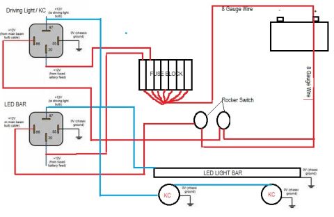
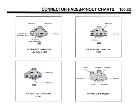
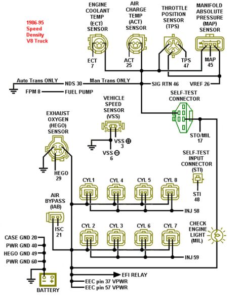
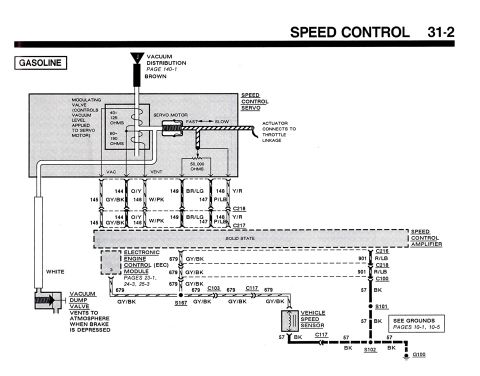



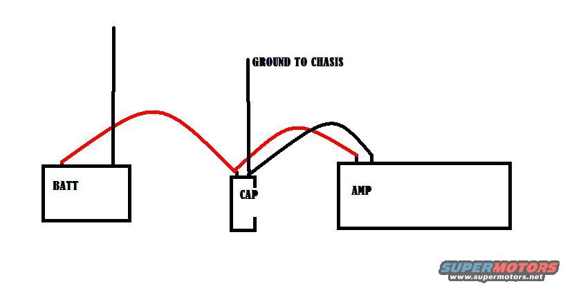
Basic car-audio wiring diagram showing battery, capacitor, and amplifier connections with ground to chassis.
Part of 1987-1991 Ford Bronco Wiring Diagrams
This is a simple hand-drawn (computer-sketched) wiring diagram showing how to install a stiffening capacitor in a car audio amplifier system. Three components are depicted as labeled boxes: BATT (battery), CAP (capacitor), and AMP (amplifier). A red power wire runs from the battery's positive terminal to the capacitor, and another red wire continues from the capacitor to the amplifier, placing the capacitor inline between the battery and the amp on the power feed. A black ground wire from the capacitor is labeled "GROUND TO CHASIS" (chassis), and a second black wire connects the capacitor area to the amplifier, indicating the amp's ground connection. A reader can learn the basic topology for wiring a car audio capacitor: positive from battery to cap, positive from cap to amp, and ground the capacitor (and amp) to the vehicle chassis. The diagram contains no fuse ratings, wire gauges, part numbers, or vehicle-specific information; it was uploaded to a 1990 Ford Bronco gallery but is generic to any car audio installation.
Is this accurate? Sign in to help verify it.
Frequently asked questions
- How do I wire a capacitor to my amp?
- Per the diagram, run a red power wire from the battery (BATT) to the capacitor (CAP), then a red wire from the capacitor to the amplifier (AMP).
- Where does the capacitor's ground wire go?
- The black ground wire from the capacitor is labeled 'GROUND TO CHASIS,' meaning it grounds to the vehicle chassis.
- Does the capacitor go before or after the amplifier?
- The capacitor is placed inline between the battery and the amplifier on the power wire.
- How is the amplifier grounded in this diagram?
- A black wire runs from the capacitor/ground point to the amplifier, sharing the chassis ground connection.






No comments yet.