130 Amp Alternator Wiring Diagram - 6 Gauge Wire, 175A Mega Fuse to Solenoid
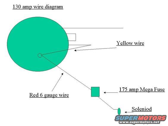
Hand-drawn 130-amp alternator upgrade wiring diagram: red 6-gauge charge wire through a 175-amp Mega Fuse to the starter solenoid, plus yellow sense wire.
Part of 1992-1996 Ford Bronco Wiring Diagrams
This is a simple hand-drawn (computer-drawn) wiring diagram titled "130 amp wire diagram," uploaded to a 1993 Ford Bronco gallery. It illustrates how to wire a 130 amp component, almost certainly a 130 amp alternator, represented by a large green circle, into the vehicle's charging circuit. The diagram shows a "Yellow wire" connecting to a terminal on the upper edge of the round component. From a center terminal (the output stud), a "Red 6 gauge wire" runs down through a "175 amp Mega Fuse" (drawn as a small square) and continues to the "Soleniod" (sic, solenoid), drawn as a small oval. A reader learns the key elements of this upgrade wiring: the charge output should be run in 6-gauge red wire, protected by a 175 amp Mega Fuse, and terminated at the starter solenoid, while the yellow wire attaches to a separate terminal on the alternator. The document contains no part numbers, connector pinouts, torque specs, year/model applicability statements, or additional legend text. It appears to be one page of a multi-page set of owner-created wiring notes (companion files: aa9.jpg, wire diagram.jpg), commonly used for a 3G alternator upgrade.
Is this accurate? Sign in to help verify it.
Frequently asked questions
- What gauge wire is shown for the 130 amp charging output?
- The diagram specifies a red 6 gauge wire running from the center terminal of the 130 amp component.
- What size fuse is used in this 130 amp wiring diagram?
- A 175 amp Mega Fuse is shown inline on the red 6 gauge wire.
- Where does the red 6 gauge wire terminate?
- It runs from the component's terminal through the 175 amp Mega Fuse to the solenoid (spelled 'Soleniod' in the diagram).
- What other wire connection is shown besides the red output wire?
- A yellow wire is shown connecting to a terminal on the upper edge of the circular component.
Comments
More from this build









No comments yet.