SuperMotors SuperMotors SUPERMOTORS Search: try “orange Bronco on 35s”
Home/ Registry/ Ford/ Bronco/ 1992-1996/ “blue”/ Photo supermotors.net/registry/media/181826

1993 Ford Bronco Wiring Mod Diagram - 4 Gauge Wire & Yellow Wire Splice

Hand-drawn wiring diagram showing a 4-gauge wire and yellow wire to a connector
Hand-drawn wiring diagram showing a 4-gauge wire and yellow wire to a connectorOriginal file
Hand-drawn wiring diagram showing a 4-gauge wire and yellow wire to a connector

Reference · 1992-1996 BroncoAll 411 wiring diagrams

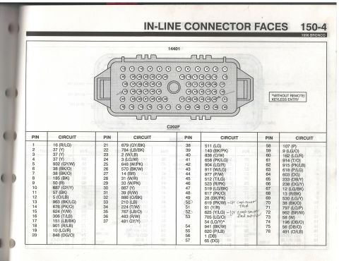
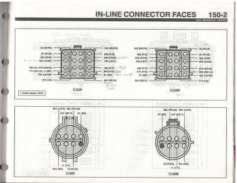
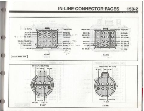
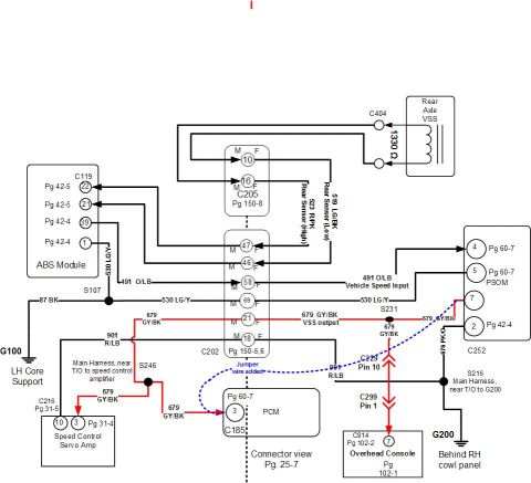
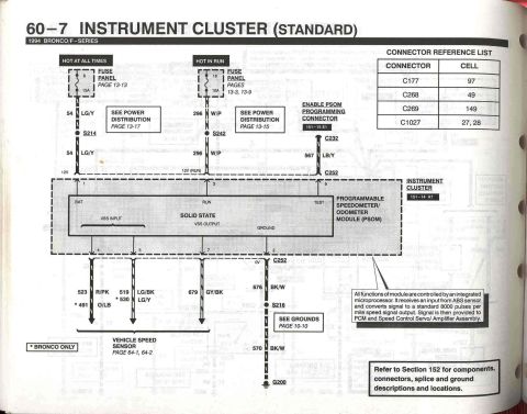
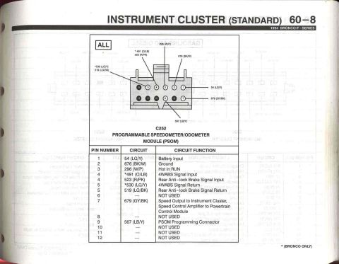
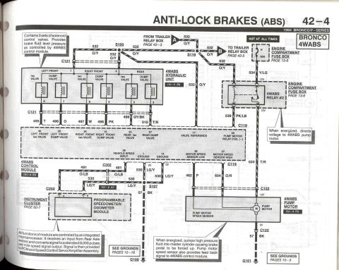
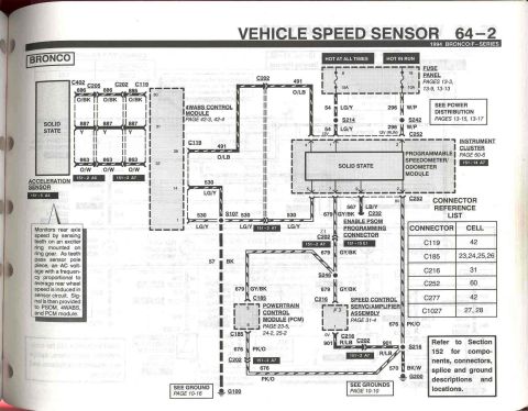
130 Amp Alternator Wiring Diagram - 6 Gauge Wire, 175A Mega Fuse to Solenoid 1993 Ford Bronco 3G 95 Amp Alternator Wiring Diagram - Fusible Link & Solenoid 1993 Ford Bronco Wiring Mod Diagram - 4 Gauge Wire & Yellow Wire Splice 1996 Ford Bronco C202F 76-Pin Connector Pinout - EVTM Page 150-4 1994 Ford Bronco/F-Series C103 & C108 Connector Pinouts - EVTM Page 150-2 1994 Ford Bronco/F-Series EVTM 150-2: C103 & C108 In-Line Connector Pinouts Ford Bronco VSS to PCM Wiring Diagram - Rear Axle Sensor, PSOM, ABS Circuit 1994 Ford Bronco/F-Series Instrument Cluster PSOM Wiring Diagram - EVTM 60-7 1994 Ford Bronco/F-Series PSOM C252 Connector Pinout - Speedometer Wiring 1994 Ford Bronco 4WABS ABS Wiring Diagram - EVTM Page 42-4 1994 Ford Bronco Vehicle Speed Sensor Wiring Diagram - EVTM Page 64-2 PSOM VSS 1996 Ford Bronco C202M In-Line Connector Pinout - 76-Pin Wiring Diagram EVTM 411wiring diagrams1992-1996 Ford Bronco More reference Chart of transmission life in miles relative to fluid temperature from 175 to 315 °FManual page Alternator buyer's guide page with photos, part numbers, amp ratings and Ford fitmentsBrochure 1996 Ford Bronco/F-150 Distributor Exploded Parts Diagram & Installation 03-07A-6Exploded parts Ford F150/F250/F350 4x4 & Bronco Truck Jacking Instructions Label E7TA-17A083-EAService procedure 1994 Ford Bronco Door Data Spec Plate - VIN, GVWR, Axle & Paint CodesSpec plate 1993 Ford V8 Serpentine Belt Routing Diagram - Pulley Layout (Q2601-E)Schematic Brake Booster to Master Cylinder Adapter Plate Blueprint - Ford Bronco SwapBlueprint 1995 Ford Bronco 5.8L Emissions/VECI Label - Vacuum Hose Routing DiagramVacuum routing Ford Bronco/F-Series Fuse 18 (10A) - Speedometer, Air Bag, Shift ControlFuse chart Rod Bolt Stretch Monitoring Chart - 8-Rod V8 Connecting Rod Bolt Record SheetTorque spec

Simple hand-drawn wiring diagram showing a 4-gauge wire and a yellow wire run to a connector with explanatory note.

Part of 1992-1996 Ford Bronco Wiring Diagrams

AI caption · Photo 162 of 195

This is a simple, hand-made illustrative diagram (drawn in a paint-style program) uploaded to document a wiring modification on the owner's 1993 Ford Bronco. It shows a large green oval representing an electrical component (likely a starter solenoid or similar device, though not labeled), with two wires running from it: a red line labeled '4 gauge' and a yellow line labeled 'Yellow wire' that runs down to a small green rectangle representing a connector. The caption at the bottom explains the modification: the owner removed the original black-and-orange wire and replaced it with 4 gauge wire, then cut the yellow wire and installed a connector, which was waterproofed. The document is part of a multi-image set (with 'wd2.jpg' and 'wire diagram.jpg') documenting the same wiring project. A reader can learn the basic routing concept of the modification, upgrading one lead to heavier 4-gauge wire and splicing the yellow wire with a weatherproofed connector, but the diagram contains no part numbers, fuse data, pinouts, or component names, so it serves as a conceptual illustration rather than a factory wiring diagram.

Is this accurate? Sign in to help verify it.

Frequently asked questions

What wire gauge was used to replace the original wire?
The diagram states the old black and orange wire was removed and replaced with 4 gauge wire.
What was done to the yellow wire?
According to the caption, the yellow wire was cut, a connector was installed, and the connection was waterproofed.
What does the diagram show?
It shows a component (green oval) with a red line labeled '4 gauge' and a yellow line labeled 'Yellow wire' running to a small connector, illustrating the wiring modification described in the caption.
Which original wire was removed in this modification?
The old black and orange wire was taken off and replaced with the 4 gauge wire.

Comments

No comments yet.

More 1992-1996 Broncos