Home/
Registry/
Ford/
Bronco/
1992-1996/
1992 Ford Bronco/
Photo
supermotors.net/registry/media/269008
Rocker Switch Wiring Diagram - RS33P/RS32P/RS31P 6-Pin Switch with 4 Relays
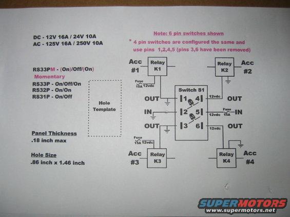
Wiring diagram showing a six-pin switch S1 controlling four relays (K1-K4) with inline fuses and accessory outputs.
Part of 1992-1996 Ford Bronco Wiring Diagrams
This document is a hand-assembled wiring diagram for wiring a 6-pin rocker switch (Switch S1) to control up to four accessories through four relays (K1-K4). It lists compatible switch part numbers and their actions: RS33PM (momentary (On)/Off/(On)), RS33P (On/Off/On), RS32P (On/On), and RS31P (On/Off). Electrical ratings are given as DC 12V 16A / 24V 10A and AC 125V 16A / 250V 10A. The diagram shows 12vdc feeds protected by 15A fuses going to the switch's IN pins (2 and 5), with OUT pins (1, 3, 4, 6) driving relays K1 through K4, each relay switching an accessory (Acc #1 through Acc #4). Ground symbols are shown for relay coil returns. A note explains that 4-pin switches are configured the same way but use pins 1, 2, 4, 5 (pins 3 and 6 removed). Mounting information is included: a hole template outline, maximum panel thickness of.18 inch, and hole size of.86 inch x 1.46 inch. A reader can learn how to wire these rocker switches with fuses and relays to control multiple accessories and how to cut the panel mounting hole.
Is this accurate? Sign in to help verify it.
Frequently asked questions
- What are the electrical ratings of the switches in this diagram?
- DC: 12V 16A / 24V 10A. AC: 125V 16A / 250V 10A.
- What switch part numbers are covered and what are their functions?
- RS33PM - (On)/Off/(On) momentary, RS33P - On/Off/On, RS32P - On/On, and RS31P - On/Off.
- What size hole is needed to mount the switch?
- The hole size is .86 inch x 1.46 inch, with a maximum panel thickness of .18 inch.
- What fuse rating is used in the wiring diagram?
- 15A fuses are shown on the 12vdc feeds to the switch and relay circuits.
- Can 4-pin switches be used with this diagram?
- Yes. The note states 4-pin switches are configured the same and use pins 1, 2, 4, 5 (pins 3 and 6 have been removed).
Comments
More from this build






No comments yet.