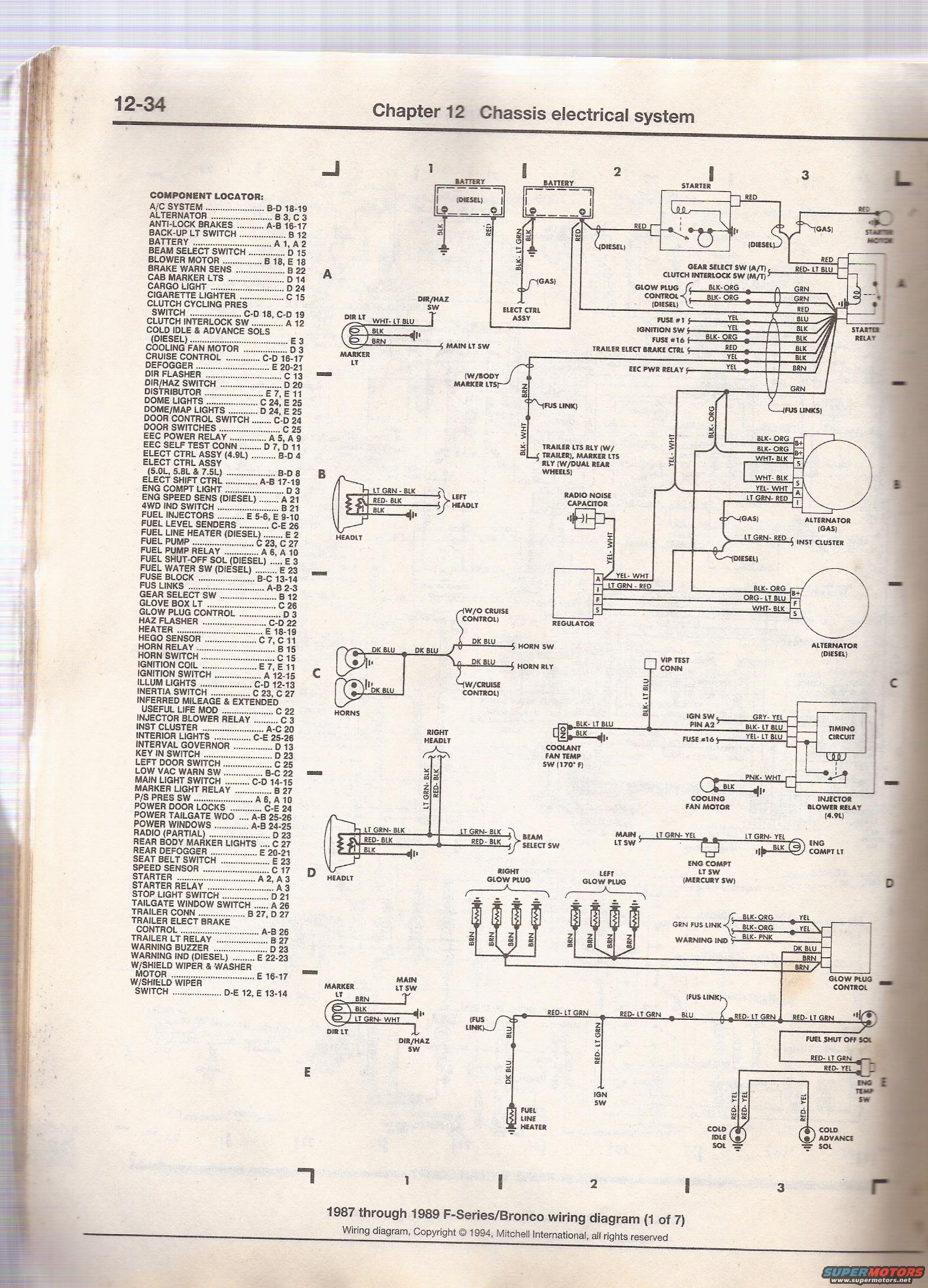
1987-1989 Ford F-Series/Bronco Wiring Diagram 1 of 7 - Component Locator
Reference · 1980-1986 BroncoAll 92 wiring diagrams
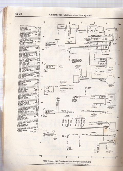







Mitchell 1987-1989 F-Series/Bronco wiring diagram (sheet 1): alphabetical component-locator index plus battery, starter, alternator and cooling-fan circuits.
Part of 1980-1986 Ford Bronco Wiring Diagrams
This is page 12-34 from Chapter 12 (Chassis electrical system) of a Haynes-style repair manual, showing sheet 1 of 7 of the 1987 through 1989 Ford F-Series/Bronco wiring diagram (copyright 1994 Mitchell International). The left column contains a complete component locator index listing electrical components alphabetically (A/C system through windshield wiper switch) with their grid coordinates (letters A-E and numbers) across the 7-sheet diagram set. The diagram itself covers the starting and charging circuits for both gas and diesel engines: batteries, starter, starter motor, starter relay, gas and diesel alternators, voltage regulator, glow plug control and glow plugs (diesel), fuel line heater, fuel shut-off solenoid, cold idle and cold advance solenoids, engine temperature switch, cooling fan motor and coolant fan temp switch (170°F), injector blower relay (4.9L), timing circuit, horns and horn relay/switch, headlights and beam select switch, marker lights, dir/haz switch, radio noise capacitor, VIP test connector, and engine compartment light. Wire colors are labeled throughout (e.g., BLK-ORG, RED-LT BLU, YEL-WHT, LT GRN-RED), along with fuse references (Fuse #1, Fuse #16) and fusible links. A reader can locate any electrical component on the diagram set and trace wire colors for starting/charging/glow plug circuits.
This document covers 1987-1989, which may differ from this 1985 Ford Bronco.
Is this accurate? Sign in to help verify it.
Frequently asked questions
- What years and models does this wiring diagram cover?
- The page states it is the '1987 through 1989 F-Series/Bronco wiring diagram (1 of 7)', so it covers 1987-1989 Ford F-Series trucks and Broncos.
- Where is the fuse block located on this wiring diagram set?
- The component locator lists the FUSE BLOCK at grid coordinates B-C 13-14.
- What circuits are shown on this first sheet?
- It shows the battery, starter, starter relay, alternator (gas and diesel), regulator, glow plug control and glow plugs, fuel line heater, fuel shut-off solenoid, cold idle and cold advance solenoids, cooling fan motor, coolant fan temp switch (170°F), injector blower relay (4.9L), horns, headlights, beam select switch, marker lights, and engine compartment light.
- Where is the EEC power relay in the diagram set?
- The component locator lists the EEC POWER RELAY at A 5 and A 9.
- What wire colors connect to the gas alternator?
- The gas alternator shows BLK-ORG to B+ terminals, WHT-BLK to S, YEL-WHT to A, and LT GRN-RED to I.






No comments yet.