1987-1989 Ford F-Series/Bronco 4.9L EEC-IV Wiring Diagram (2 of 7) - ECA Pinout

Reference · 1980-1986 BroncoAll 92 wiring diagrams
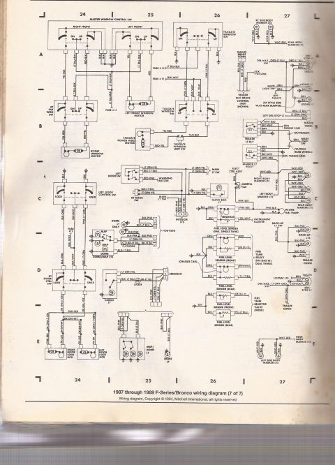
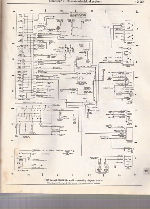
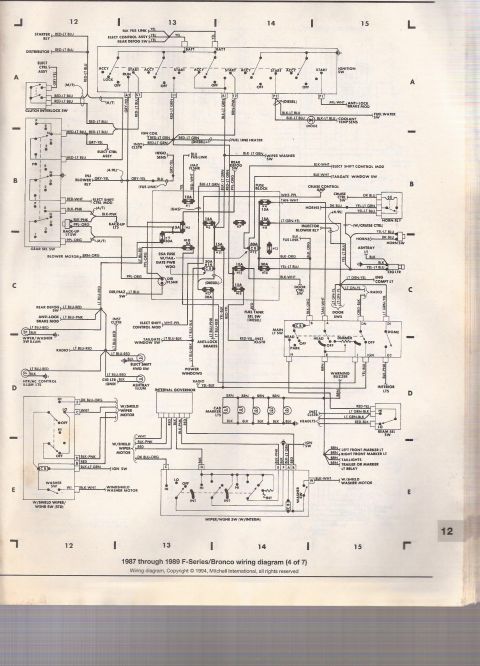
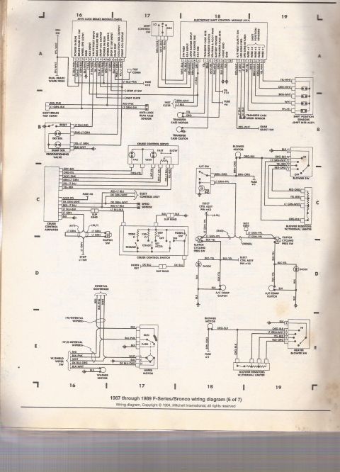
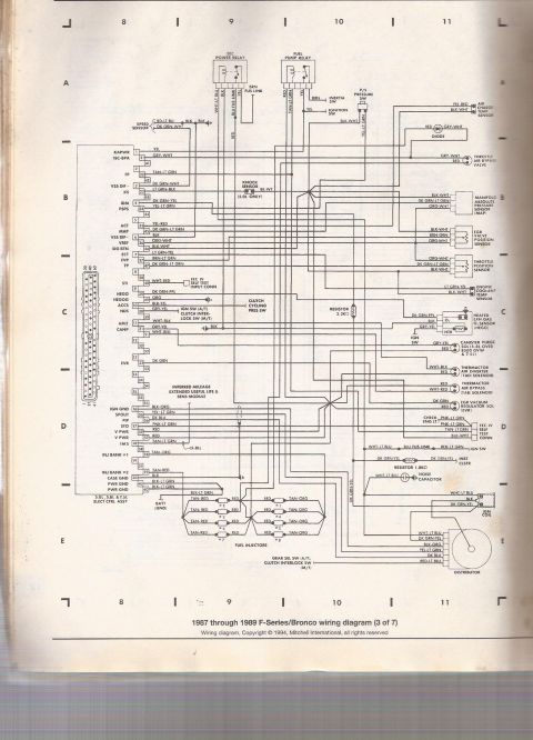
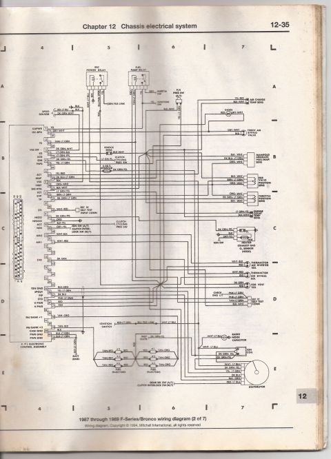
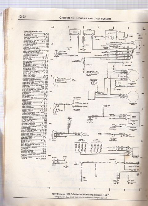

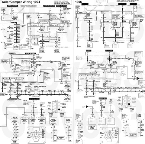






Ford F-Series/Bronco chassis electrical wiring diagram (sheet 2 of 7) showing color-coded circuits and connectors.
Part of 1980-1986 Ford Bronco Wiring Diagrams
This is page 12-35 from Chapter 12 (Chassis electrical system) of a repair manual, showing sheet 2 of 7 of the 1987 through 1989 Ford F-Series/Bronco wiring diagram (copyright 1994 Mitchell International). The diagram covers the EEC-IV engine control wiring for the 4.9L Electronic Control Assembly (ECA). It shows the 60-pin ECA connector with pin numbers, signal names (KAPWR, ISC-BPA, FS, VSS, KS, ACT, MAP, VREF, SIG RTN, ECT, EVP, TP, STI, HEGO, SPOUT, PIP, STO, V PWR, INJ BANK #1/#2, grounds, etc.) and wire colors for each circuit. Connected components include the EEC power relay, fuel pump relay, inertia switch, ignition switch, speed sensor, knock sensor, clutch cycling pressure switch, air charge temperature sensor, throttle air bypass valve, MAP sensor, EGR valve position sensor, throttle position sensor, engine coolant temperature sensor, heated oxygen sensor (HEGO), thermactor air diverter and bypass solenoids, EGR vent solenoid, EEC-IV self-test connector, check engine light, radio noise capacitor, ignition coil, distributor, and all six fuel injectors with their wire colors. A reader can trace any 4.9L EEC-IV circuit by pin number and wire color for diagnosis of engine management wiring on these trucks.
This document covers 1987-1989, which may differ from this 1985 Ford Bronco.
Is this accurate? Sign in to help verify it.
Frequently asked questions
- What years and models does this wiring diagram cover?
- It is labeled '1987 through 1989 F-Series/Bronco wiring diagram (2 of 7)', covering the 4.9L Electronic Control Assembly circuits.
- What wire colors go to the fuel injectors on the 4.9L?
- Injectors #2, #4, and #6 use TAN-RED to RED wires, while injectors #1, #3, and #5 use RED to TAN-ORG wires; INJ BANK #1 (pin 58) is TAN-ORG and INJ BANK #2 (pin 59) is TAN-RED at the ECA.
- Which ECA pins are power and ground on the 4.9L computer?
- Pins 37 and 57 are V PWR (RED wires), pin 1 is KAPWR (YEL), pin 20 is CASE GND (BLK), pins 40 and 60 are PWR GND (BLK-LT GRN), and pin 16 is IGN GND (BLK-ORG).
- What wire colors connect to the throttle position sensor?
- The throttle position sensor uses ORG-WHT, DK GRN-LT GRN, and BLK-WHT wires; TP signal arrives at ECA pin 47 (DK GRN-LT GRN).
- What wires run to the distributor on this diagram?
- The distributor connects via WHT-LT BLU, DK GRN-YEL, YEL-LT GRN, DK BLU, BLK-ORG, and RED-LT BLU wires; PIP is DK BLU at pin 56 and SPOUT is YEL-LT GRN at pin 36.






No comments yet.