1987-1989 Ford F-Series/Bronco Wiring Diagram 6 of 7 - Instrument Cluster & Fuel

Reference · 1980-1986 BroncoAll 92 wiring diagrams
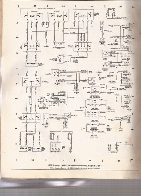
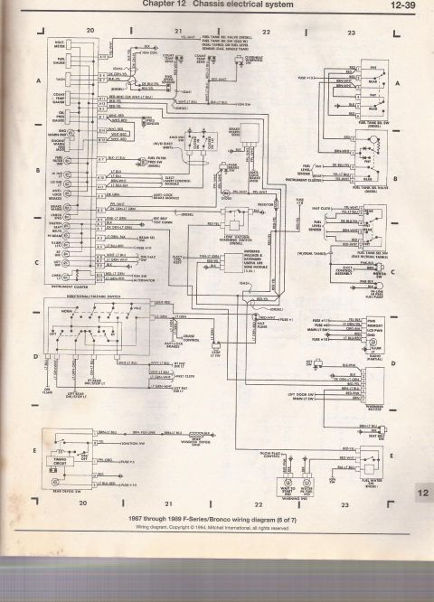
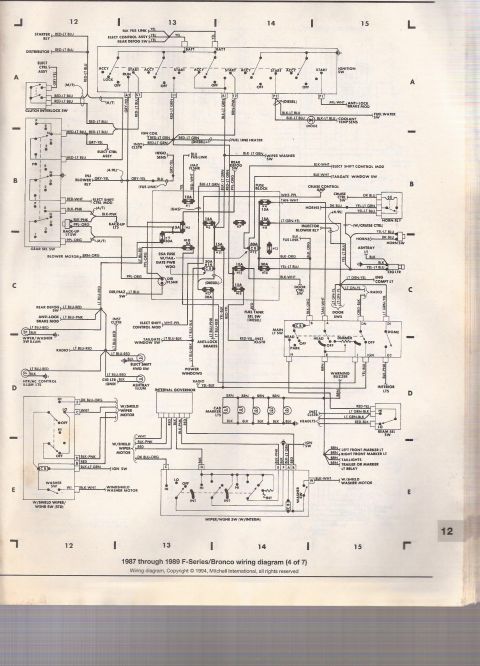
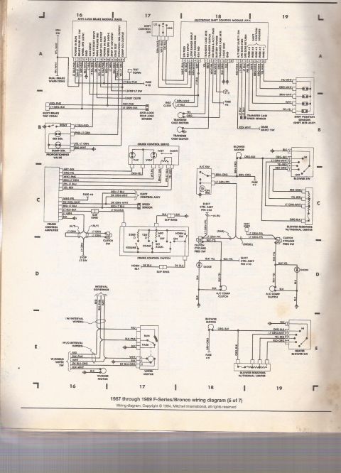
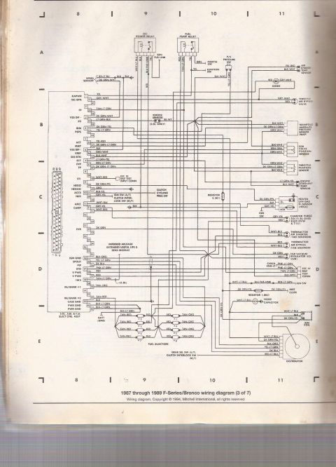
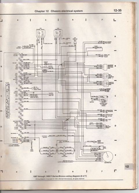
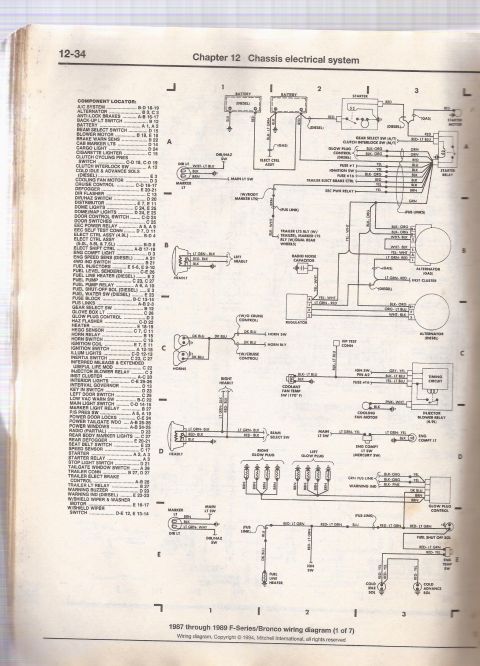

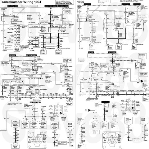






Mitchell wiring diagram (6 of 7) for 1987-1989 Ford F-Series/Bronco covering door/jamb switches, alternator, instrument cluster, warning lamps and turn signals.
Part of 1980-1986 Ford Bronco Wiring Diagrams
This is page 12-39 from Chapter 12 (Chassis electrical system) of a repair manual, showing sheet 6 of 7 of the 1987 through 1989 Ford F-Series/Bronco wiring diagram (copyright 1994 Mitchell International). The schematic covers the instrument cluster and warning/indicator circuits, including the voltmeter, fuel gauge, tachometer, coolant temperature and oil pressure gauges, engine warning indicators, fuel filter indicator (diesel), 4WD hi/lo indicators, anti-lock brake warning, brake warning, check engine, seat belt, high beam, illumination, turn signal, and charge indicator lights with cluster connector pins (A1-A13, B1-B14) and wire colors. It also details the directional/hazard switch wiring to front and rear turn/stop lamps, the rear window defogger switch and timing circuit, fuel tank selector switch and valve wiring for diesel and gas dual-tank systems, fuel level senders, inertia switch and in-line high-pressure fuel pump, partial radio power/memory/illumination wiring, the warning buzzer (key, door, seat belt inputs), fuel/water separator switch (diesel), glow plug control with wait-to-start and water-in-fuel indicators, and the low vacuum warning switch (diesel). Fuse references include Fuses #1, #5, #8, #10, #11, #15, and #18. Readers can trace wire colors, connector pin numbers, and circuit paths for troubleshooting these systems.
This document covers 1987-1989, which may differ from this 1985 Ford Bronco.
Is this accurate? Sign in to help verify it.
Frequently asked questions
- What years and models does this wiring diagram cover?
- The caption states it is the 1987 through 1989 F-Series/Bronco wiring diagram, sheet 6 of 7.
- What fuse powers the instrument cluster illumination lights?
- The ILLUM LTS circuit connects via pin A4 with an LT BLU-RED wire to Fuse #10.
- What wire colors are used on the fuel tank selector switch for gas dual-tank trucks?
- The FUEL TANK SEL SW (GAS W/DUAL TANKS) shows YEL-WHT and YEL-LT BLU to the instrument cluster, DK BLU-YEL (front) and BRN-WHT (rear) to the fuel level senders, plus RED and RED-WHT wires.
- How is the rear window defogger switch wired?
- The REAR DEFOG SW has terminal L (BRN-LT BLU through a BRN fusible link to the rear window defog grid), B (YEL to the ignition switch), I (PPL-ORG to Fuse #5), G (BLK to ground), and S (LT BLU-RED to Fuse #10), with an internal timing circuit.
- What circuits connect to the warning buzzer?
- The warning buzzer connects to the key switch (BLK-PNK, pin 1), ground (BLK, pin 2), DK GRN-LT GRN (pin 3), RED-YEL (pin 4), BRN-LT BLU (pin 5), the left door switch (RED-PNK, pin 6), and the main light switch (BRN, pin 7).






No comments yet.