1987-1989 Ford F-Series/Bronco Wiring Diagram 5 of 7 - RABS, 4x4 Shift, Cruise
Reference · 1980-1986 BroncoAll 92 wiring diagrams
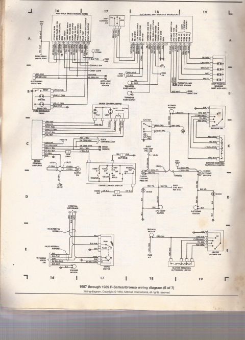
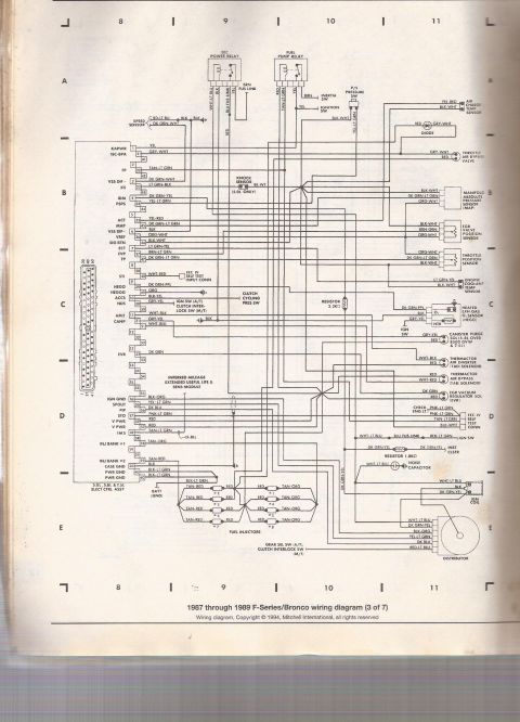
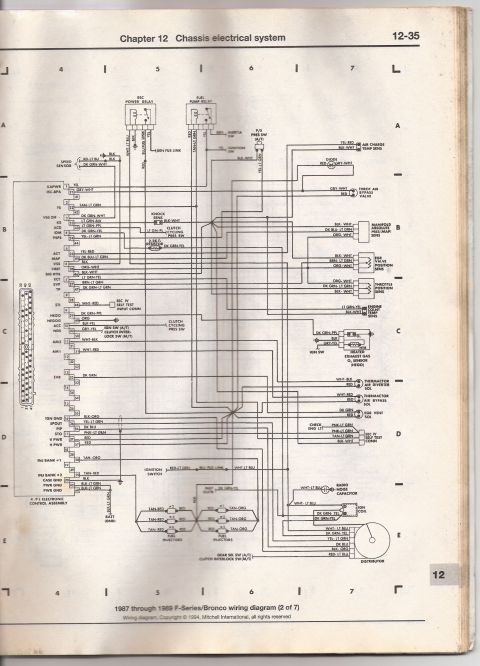
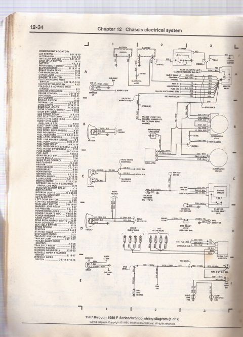

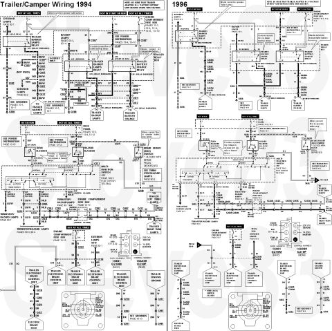






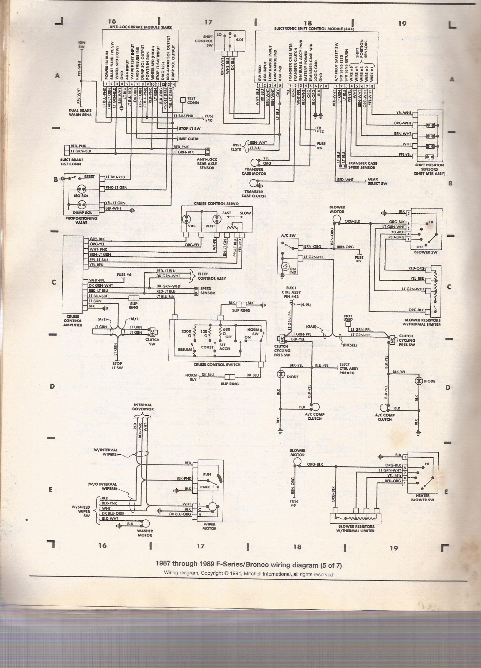
Mitchell wiring diagram (5 of 7) for 1987-1989 Ford F-Series/Bronco covering anti-lock brakes, transfer-case speed sensor, blower motor and cruise control circuits.
Part of 1980-1986 Ford Bronco Wiring Diagrams
This is page 5 of 7 of a Mitchell International (copyright 1994) wiring diagram set covering 1987 through 1989 Ford F-Series trucks and Broncos. The page presents several vehicle electrical systems in schematic form with full wire color codes and connector pinouts. Systems shown include: the Anti-Lock Brake Module (RABS) with its 14-pin connector, dual brake warning sensor, proportioning valve (ISO/DUMP solenoids, reset), electric brake test connector, and rear axle anti-lock sensor; the Electronic Shift Control Module (4X4) with shift control switch, transfer case motor, transfer case clutch, transfer case speed sensor, gear select switch, and shift position sensors (shift motor assembly); the cruise control system, including the cruise control amplifier, servo (VAC/VENT), speed sensor, clutch switch, slip rings, and cruise control switch with 2200/120/680-ohm resistor values; the A/C and heater blower circuits, with A/C switch, clutch cycling pressure switches (gas, diesel, 4.9L variants), A/C compressor clutch diodes, blower motors, blower switches, and blower resistors with thermal limiter; and the windshield wiper/washer system with interval governor, wiper switch, wiper motor, and washer motor. Fuse references include Fuse #6, #9, #10 and circuit breaker #12. A reader can trace wire colors, pin numbers, and circuit paths for diagnosing these systems.
This document covers 1987-1989, which may differ from this 1985 Ford Bronco.
Is this accurate? Sign in to help verify it.
Frequently asked questions
- What year Ford trucks does this wiring diagram cover?
- The caption states it is a '1987 through 1989 F-Series/Bronco wiring diagram (5 of 7)', copyright 1994 Mitchell International.
- What wire colors connect to the RABS anti-lock rear axle sensor?
- The anti-lock rear axle sensor connects with RED-PNK and LT GRN-BLK wires, which also run to the electric brake test connector.
- Which fuses are referenced on this page?
- Fuse #10 (stop light switch/RABS circuit), Fuse #6 (shift control module and cruise WHT-PPL feed), Fuse #9 (A/C switch and blower motor circuits), and circuit breaker CB #12 for the electronic shift control module.
- What resistor values are in the cruise control switch?
- The cruise control switch shows 2200 ohm, 120 ohm, and 680 ohm resistors, with OFF, ON, RESUME, COAST, and SET ACCEL positions.
- What wire colors go to the shift position sensors on the 4x4 electronic shift module?
- Wire #5 PPL-YEL, Wire #4 WHT, Wire #3 BRN-WHT, Wire #2 ORG-WHT, and Wire #1 YEL-WHT connect to the shift position sensors (shift motor assembly).






No comments yet.