1987-1989 Ford F-Series/Bronco EEC-IV Wiring Diagram (3 of 7) - ECA Pinout

Reference · 1980-1986 BroncoAll 92 wiring diagrams
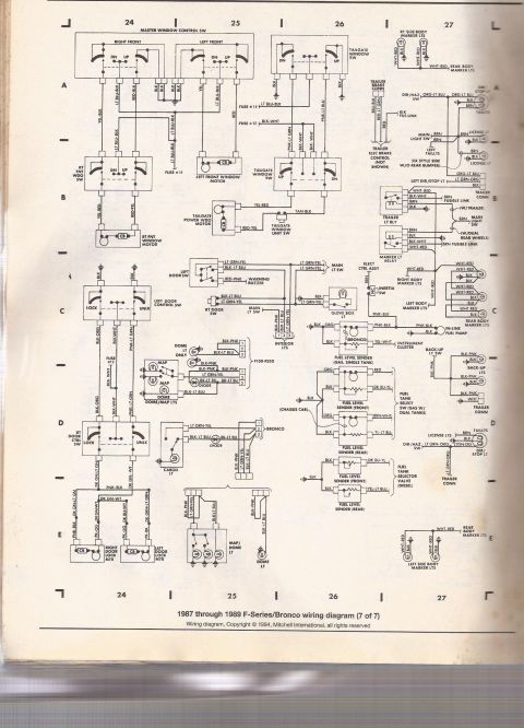
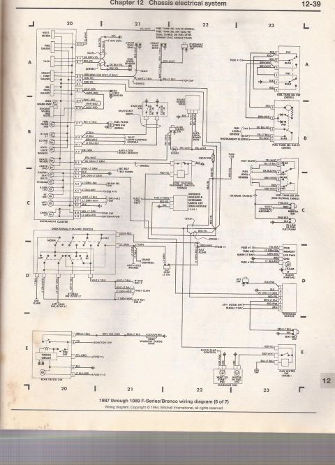
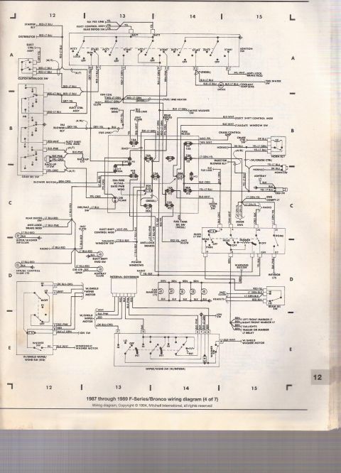
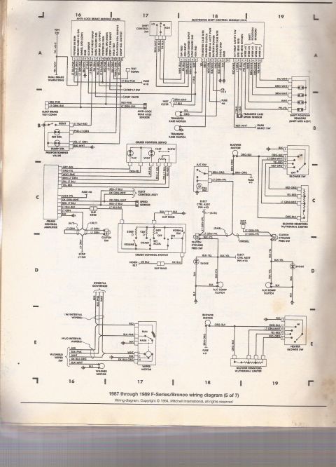
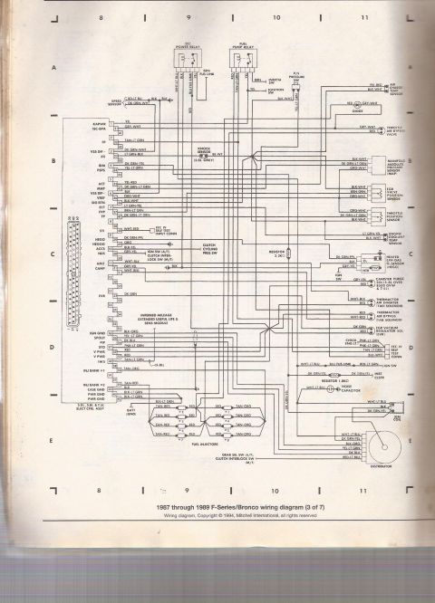
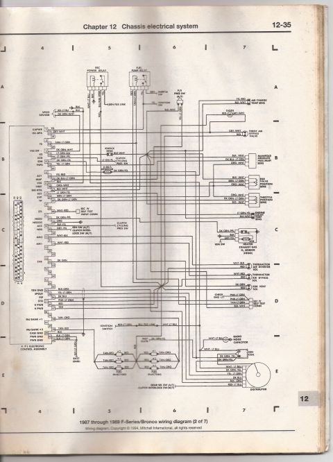
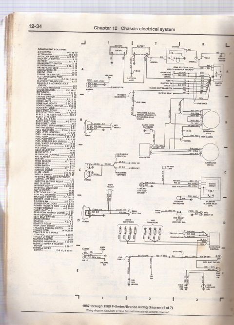







Mitchell wiring diagram (3 of 7) for 1987-1989 Ford F-Series/Bronco covering EEC engine management: TPS, knock sensor, clutch cycling switch, injectors and solenoids.
Part of 1980-1986 Ford Bronco Wiring Diagrams
This scanned page is sheet 3 of 7 of the 1987 through 1989 Ford F-Series/Bronco wiring diagram set (copyright 1994, Mitchell International). It depicts the EEC-IV engine control system wiring for the 5.0L, 5.8L, and 7.5L electronic engine control assembly (ECA), showing the 60-pin ECA connector with pin numbers, signal names (KAPWR, ISC-BPA, FP, KS, IDM, PSPS, ACT, MAP, VREF, SIG RTN, ECT, EVP, TP, STI, HEGO, ACCS, NDS, AM2, CANP, EVR, IGN GND, SPOUT, PIP, STO, V PWR, IMS, INJ BANK #1/#2, CASE GND, PWR GND), and wire color codes for each circuit. Connected components include the EEC power relay, fuel pump relay, inertia switch, ignition switch, power steering pressure switch, speed sensor, knock sensor (5.0L only), air charge temp sensor, throttle air bypass valve, MAP sensor, EGR valve position sensor, throttle position sensor, engine coolant temp sensor, heated oxygen sensor (HEGO), canister purge solenoid (5.8L over 8500 GVW & 7.5L), thermactor TAD/TAB solenoids, EGR vacuum regulator solenoid, EEC-IV self test connector with check engine light, noise capacitor, ignition coil, distributor, and the eight fuel injectors (banks #1 and #2). Resistor values of 2.2 kΩ and 1.8 kΩ are noted.
This document covers 1987-1989, which may differ from this 1985 Ford Bronco.
Is this accurate? Sign in to help verify it.
Frequently asked questions
- What years and vehicles does this wiring diagram cover?
- It is labeled '1987 through 1989 F-Series/Bronco wiring diagram (3 of 7)' and applies to the 5.0L, 5.8L & 7.5L electronic control assembly.
- What wire colors go to the fuel injectors?
- Injectors #2, #3, #6 and #7 use TAN-RED wires and injectors #1, #4, #5 and #8 use TAN-ORG wires, each paired with a RED feed wire.
- Which ECA pins are power and ground?
- Pins 37 and 57 are V PWR (RED), pin 20 is CASE GND (BLK), pins 40 and 60 are PWR GND (BLK-LT GRN), and pin 16 is IGN GND (BLK-ORG).
- What wire colors connect to the throttle position sensor?
- The throttle position sensor uses ORG-WHT, DK GRN-LT GRN, and BLK-WHT wires.
- Is the knock sensor used on all engines?
- No: the diagram notes the knock sensor (BK-WT wire) is '5.0L ONLY'.






No comments yet.