Home/
Registry/
Ford/
Bronco/
1980-1986/
“THE DESTROYER”/
Photo
supermotors.net/registry/media/290824
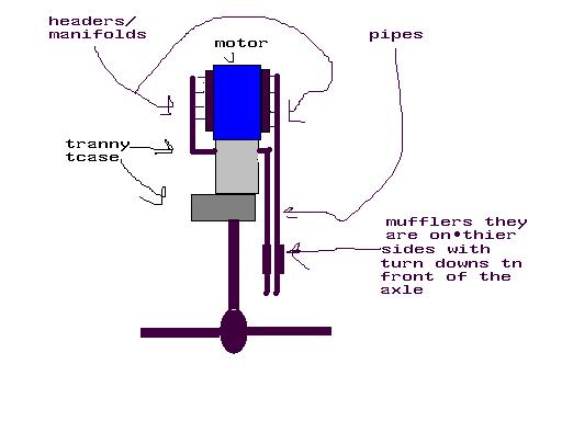
1986 Ford Bronco Dual Exhaust Routing Schematic - Mufflers & Turn-Downs Layout
Reference · 1980-1986 BroncoAll 34 schematics





Rough schematic of an exhaust layout labeling headers/manifolds, tranny/tcase, pipes and side-exit mufflers.
Part of 1980-1986 Ford Bronco Schematics
This document is a simple hand-drawn schematic (created in a basic paint program) illustrating a proposed or existing dual exhaust routing layout on a vehicle drivetrain, viewed from the front. The drawing shows a blue rectangle labeled "motor" (engine) with "headers/manifolds" indicated on both sides. Below the engine, gray blocks represent the "tranny tcase" (transmission and transfer case). Two vertical lines labeled "pipes" run down alongside the drivetrain to the rear. A callout notes the "mufflers" positioning: "they are on thier sides with turn downs tn front of the axle," indicating the mufflers are mounted sideways with turn-down outlets located ahead of the rear axle (shown at the bottom as a horizontal line with a differential oval). A reader can learn the intended general routing concept: exhaust exits the headers/manifolds on each side of the engine, pipes run rearward past the transmission/transfer case, and side-mounted mufflers with turn-downs dump just in front of the axle. The document contains no part numbers, dimensions, torque specs, pipe diameters, or year/model identification; it is a conceptual layout sketch rather than a formal factory diagram.
Is this accurate? Sign in to help verify it.
Frequently asked questions
- Where are the mufflers located in this exhaust layout?
- The mufflers are mounted on their sides with turn-downs in front of the axle.
- Where do the exhaust pipes connect at the engine?
- The pipes connect to headers/manifolds on either side of the motor.
- What drivetrain components are shown in the schematic?
- The schematic shows the motor, the tranny/tcase (transmission and transfer case), exhaust pipes, mufflers, and the rear axle with differential.
- Is this a single or dual exhaust setup?
- The drawing shows pipes routed on both sides of the drivetrain with mufflers on each side, indicating a dual exhaust arrangement.
No comments yet.