Home/
Registry/
Ford/
Bronco/
1980-1986/
“THE DESTROYER”/
Photo
supermotors.net/registry/media/586719
1986 Ford Bronco & F-Series Wiring Diagram Part 1 - Chassis Electrical, Fuses
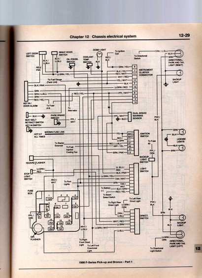
Manual chassis wiring diagram for 1986 Ford F-Series/Bronco showing lighting, ignition and instrument circuits with color codes.
This is page 12-29 from Chapter 12 (Chassis electrical system) of a Haynes-style repair manual, showing Part 1 of the chassis wiring diagram for the 1986 Ford F-Series Pick-up and Bronco. The diagram traces circuits for the dome light and door switches, oil pressure and coolant temperature switches, instrument cluster connector (with numbered pins 1-14 and wire colors such as GRN/YEL, BLK/YEL, RED/WHT, YEL/WHT, Lt.GRN/RED, PPL/WHT), key-in/door alarm, seat belt retract switch, park brake switch, dual brake warning sensor, ignition switch terminals (BATT, I1, ST, A2, P1, I2 with wire colors), backup light switch, light switch, stop light switch, hazard and directional (DIR) flashers, directional switch, and exterior lamps including directional/park/tail lights (left and right), backup lights, and license lights. It also depicts the fuse box layout with positions 1-18 and amp ratings (e.g., #1 15A, #9 30A, #10 5A, #12 25A, #14 25A, #15 10A, #16 30A, #17 20A, #18 15A). Wire color codes are labeled throughout, making this useful for tracing lighting, ignition, and warning-circuit wiring on 1986 F-Series trucks and Broncos.
Is this accurate? Sign in to help verify it.
Frequently asked questions
- What vehicles does this wiring diagram cover?
- The diagram is labeled '1986 F-Series Pick-up and Bronco - Part 1' and appears on page 12-29 of Chapter 12, Chassis electrical system.
- What fuse ratings are shown in the fuse box on this diagram?
- Fuse positions shown include: 1 (15A), 4 (15A), 5 (15A), 6 (15A), 8 (15A), 9 (30A), 10 (5A), 11 (15A), 12 (25A), 14 (25A), 15 (10A), 16 (30A), 17 (20A), and 18 (15A).
- What ignition switch terminals and wire colors are shown?
- The ignition switch shows terminals BATT (YEL), BATT/I1 (RED/Lt.GRN), ST (RED/Lt.BLU), A2 (GRY/YEL), P1, and I2 (BRN/PNK).
- Which circuits are included on this page of the diagram?
- It covers the dome light, door switches, oil pressure and coolant temperature switches, instrument cluster connector, key-in/door alarm, seat belt retract switch, park brake switch, dual brake warning sensor, ignition switch, backup light switch, light switch, stop light switch, hazard and directional flashers, directional switch, backup lights, license lights, and directional/park/tail lights.
- What wire colors go to the dual brake warning sensor?
- The dual brake warning sensor is shown with a PPL/WHT wire and a BLK wire.
Comments
More from this build








No comments yet.