Home/
Registry/
Ford/
Bronco/
1992-1996/
1995 Ford Bronco/
Photo
supermotors.net/registry/media/295656
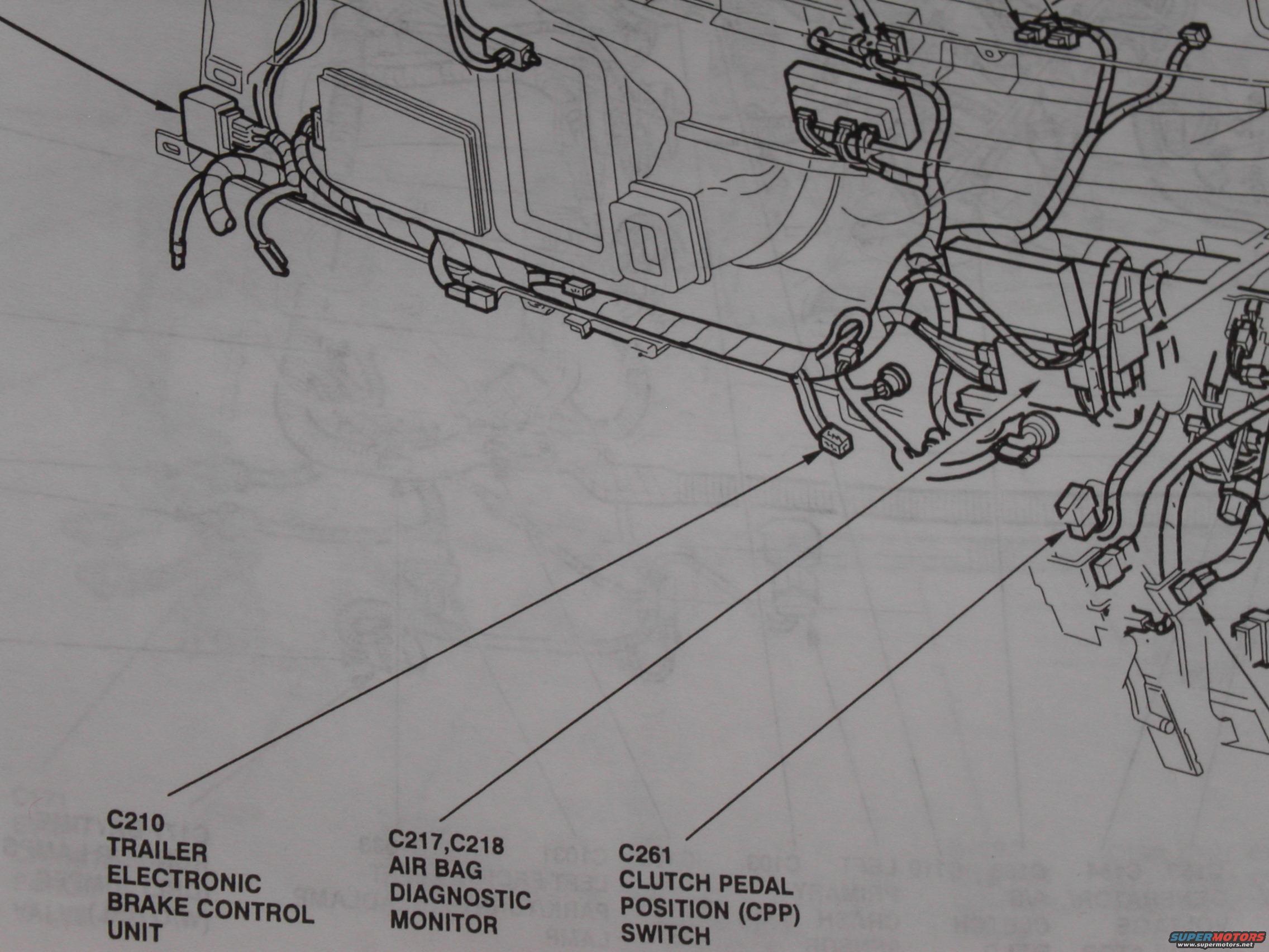
Ford Bronco EVTM Connector Locations: C210, C217/C218 Air Bag Monitor, C261 CPP
Reference · 1992-1996 BroncoAll 411 wiring diagrams



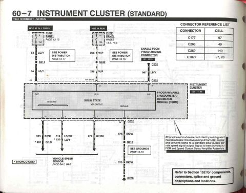
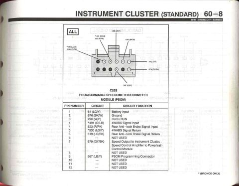
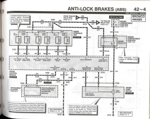
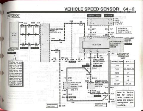









Wiring harness routing diagram showing connectors C210, C217/C218 and C261 with trailer brake, air bag and clutch position callouts.
Part of 1992-1996 Ford Bronco Wiring Diagrams
This document is a scanned page from a Ford Electrical and Vacuum Troubleshooting Manual (EVTM) showing a component location illustration for the area behind/under the instrument panel and dash harness. The line-art drawing depicts the dash wiring harness routed along the underside of the instrument panel, with multiple connectors, brackets, and modules illustrated in perspective. Three leader arrows identify specific electrical connectors and components: connector C210 for the Trailer Electronic Brake Control Unit (shown at a connector on the left/driver side area of the harness), connectors C217 and C218 for the Air Bag Diagnostic Monitor (pointing to a module mounted behind the dash), and connector C261 for the Clutch Pedal Position (CPP) Switch (pointing to a connector near the pedal/steering column support area on the right of the drawing). A reader can use this page to locate these three connectors and their associated components when diagnosing trailer brake controller wiring, the air bag (SRS) diagnostic monitor, or the clutch pedal position switch circuit on a manual-transmission vehicle. No fuse values, wire colors, pinouts, or year/model statements are visible on this cropped page.
Is this accurate? Sign in to help verify it.
Frequently asked questions
- What connector is used for the Trailer Electronic Brake Control Unit?
- Connector C210 is identified as the Trailer Electronic Brake Control Unit connector, shown on the dash harness on the left side of the illustration.
- Which connectors go to the Air Bag Diagnostic Monitor?
- Connectors C217 and C218 connect to the Air Bag Diagnostic Monitor, shown mounted behind the instrument panel.
- What is connector C261?
- C261 is the connector for the Clutch Pedal Position (CPP) Switch, located near the pedal area on the right side of the diagram.
- Does this page show fuse ratings or wire colors?
- No. It is a component/connector location illustration only; no fuse amperages, wire colors, or pin assignments are shown.






No comments yet.