Home/
Registry/
Ford/
Bronco/
1987-1991/
1991 Ford Bronco/
Photo
supermotors.net/registry/media/300771
Bendix Hydro-Boost Brake Booster Cutaway Diagram - Generating Pressure
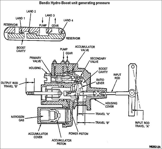
Cutaway schematic of a Bendix Hydro-Boost unit generating pressure, labeling reservoir lands, valves, accumulator, and travel dimensions.
This document is a labeled cutaway schematic of a Bendix Hydro-Boost hydraulic brake booster unit shown in its pressure-generating (applied) state. The top portion shows a detailed cross-section of the spool valve, identifying Land 1 through Land 4, the reservoir ports (two locations), the pump port, the gear port, and the boost cavity. The main lower illustration is a full cutaway of the Hydro-Boost assembly with callouts for the primary valve, secondary valve, accumulator valve, housing, housing cover, boost cavity, ratio lever, power piston, input rod, and output rod. The nitrogen-gas-charged accumulator is also detailed, with labels for the nitrogen gas chamber, accumulator piston, and accumulator cover. Motion relationships are indicated with dimension arrows: input rod travel "A", travel "A" and travel "B" at the ratio lever/power piston area, and output rod travel "B", illustrating how pedal input travel is translated through the ratio lever to output rod movement. The figure reference number H6262-2A appears in the lower right corner. A reader can learn the internal component layout of the Hydro-Boost unit, the hydraulic porting of its spool valve during pressure generation, and how input and output rod travel relate through the ratio lever. It was uploaded as part of a multi-page Hydro-Boost reference set for a 1991 Ford Bronco.
Is this accurate? Sign in to help verify it.
Frequently asked questions
- What does this diagram show?
- A labeled cutaway of a Bendix Hydro-Boost unit generating pressure, including the spool valve lands, boost cavity, accumulator, ratio lever, power piston, and input/output rods.
- What are the labeled parts of the Hydro-Boost spool valve?
- The spool valve cutaway shows Land 1, Land 2, Land 3, and Land 4, with reservoir ports, a pump port, a gear port, and the boost cavity.
- What charges the Hydro-Boost accumulator?
- The diagram labels nitrogen gas inside the accumulator, along with the accumulator piston and accumulator cover.
- How is input rod motion related to output rod motion?
- The diagram shows input rod travel "A" acting through a ratio lever on the power piston, producing output rod travel "B", with travel "A" and travel "B" dimensions marked at the lever.
- What valves are inside the Hydro-Boost unit?
- The diagram labels a primary valve, a secondary valve, and an accumulator valve.
Comments
More from this build








No comments yet.