Home/
Registry/
Ford/
Bronco/
1987-1991/
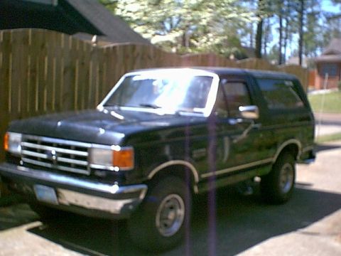
1991 Ford Bronco/
Photo
supermotors.net/registry/media/300773
Bendix Hydro-Boost Leak Identification Diagram - Seal Leak Locations (Ford)

Diagram identifying Bendix Hydro-Boost leak points, labeling the spool plug, piston, accumulator, housing, and input seals.
This document is a labeled schematic diagram titled "Bendix Hydro-Boost Leak Identification," filed with a 1991 Ford Bronco. It shows a side view of a Bendix Hydro-Boost hydraulic brake booster assembly with arrows and drip symbols identifying the locations where fluid leaks can occur and which seal is responsible. The hydraulic line connections are labeled: RETURN TO RESERVOIR, FROM PUMP, and TO GEAR (steering gear). Potential leak points are labeled by seal name: the SPOOL PLUG SEAL at the top-left of the housing, the PISTON SEAL at the lower front, the ACCUMULATOR SEAL at the bottom center, the HOUSING SEAL where the housing halves meet, and the INPUT SEAL at the pushrod/input shaft end. Drip symbols beneath each location indicate where leaking fluid would appear. The figure carries the identification number H6268-B. A reader can use this diagram to visually match the location of an external power steering fluid leak on a Hydro-Boost unit to the specific internal seal that has failed, aiding in diagnosis and deciding whether to reseal or replace the unit. The document contains no year, model, part number, or torque data — it is purely a leak-location identification illustration, one page of a multi-page Hydro-Boost reference set.
Is this accurate? Sign in to help verify it.
Frequently asked questions
- What seals can leak on a Bendix Hydro-Boost unit?
- The diagram identifies five leak-prone seals: the spool plug seal, piston seal, accumulator seal, housing seal, and input seal.
- Where is the input seal located on the Hydro-Boost?
- The input seal is at the pushrod/input shaft end of the unit, on the side facing the brake pedal linkage.
- What are the hydraulic line connections on the Hydro-Boost booster?
- Three connections are labeled: return to reservoir, from pump, and to gear (steering gear).
- Where is the accumulator seal leak point?
- The accumulator seal is shown at the bottom center of the unit, with drip symbols indicating fluid would leak downward from that area.
- What is the figure reference number of this diagram?
- The diagram is identified as H6268-B.
Comments
More from this build






No comments yet.