Home/
Registry/
Ford/
Bronco/
1987-1991/
1991 Ford Bronco/
Photo
supermotors.net/registry/media/300780
Bendix Hydro-Boost Reserve Operation Diagram - Accumulator Valve Schematic

Reference · 1987-1991 BroncoAll 110 schematics

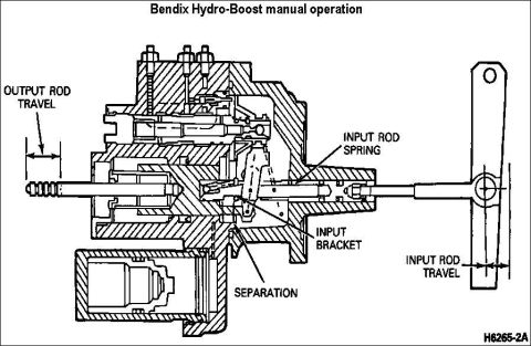
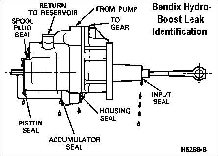
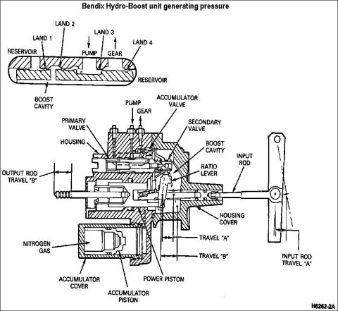
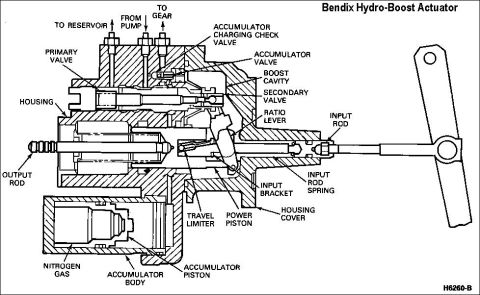
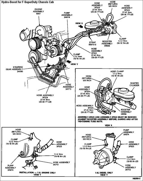




Cutaway schematic of Bendix Hydro-Boost reserve operation showing the accumulator charging check valve, lever travel, and boost cavity.
Part of 1987-1991 Ford Bronco Schematics
This document is a cross-sectional schematic illustrating the reserve (accumulator) operation of a Bendix Hydro-Boost hydraulic brake booster. The diagram shows the internal cutaway of the booster unit with the input lever/linkage on the right side. Labeled callouts identify the accumulator charging check valve on the upper left of the housing, the lever travel dimension near the input lever, and the boost cavity within the unit. A key callout explains the reserve function: as the lever travels, the accumulator valve is contacted, releasing stored fluid pressure to the boost cavity, this is how the Hydro-Boost provides reserve brake assist when normal power steering pump pressure is unavailable (e.g., engine off or pump failure). The lower portion of the scan is obscured by a gray block, so any caption text there is unreadable. The document appears to be one page of a multi-page Hydro-Boost reference set uploaded to a 1991 Ford Bronco gallery; the diagram itself does not state any specific vehicle year, make, or model, only the Bendix Hydro-Boost system. Readers can learn the location of the accumulator charging check valve and understand mechanically how pedal (lever) travel triggers the accumulator valve to deliver reserve boost pressure.
Is this accurate? Sign in to help verify it.
Frequently asked questions
- How does the Bendix Hydro-Boost provide reserve brake assist?
- According to the diagram, as the lever travels, the accumulator valve is contacted, releasing stored fluid pressure to the boost cavity to provide assist.
- What components are labeled in this Hydro-Boost reserve operation diagram?
- The diagram labels the accumulator charging check valve, lever travel, the accumulator valve (which releases fluid pressure), and the boost cavity.
- Where is the accumulator charging check valve located on the Hydro-Boost unit?
- The callout points to the upper-left area of the booster housing in the cutaway view.
- What triggers the release of accumulator pressure in the Hydro-Boost?
- Lever travel, when the input lever moves, it contacts the accumulator valve, which releases fluid pressure to the boost cavity.






No comments yet.